
Installation guide


LMU Users Guide
V1.0.6 December 10 2009
Copyright ©CalAmp DataCom Inc 2009
- 15 - CalAmp Proprietary & Confidential
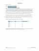
Enable Temperature Sensors:
AT$APP PARAM 1024,51,64,64
Enable ID Tag
AT$APP PARAM 1024,51,64,0
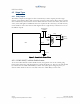
The LMU-2500™ can work with up to eight (reference 0-7) Maxim DS28EA00 1-wire
temperature sensors in a chain configuration interconnected by a 3-wire bus. Upon boot-up,
the LMU executes a discovery procedure to detect the number of connected DS28EA00
devices. The LMU assigns each sensor a reference number starting with zero (0) for the
sensor closest to the LMU in the sensor chain and incrementing for each sensor down the
chain up to seven (7). During operation, the LMU sequentially polls each sensor for its
temperature reading; one sensor every 10 seconds. If all eight sensors are deployed, each
sensor will be polled every 80 seconds. A poll involves commanding the sensor to perform
the temperature conversion and 1-sec later reading the results of the conversion
4.2.7 Analog to Digital Inputs
The LMU’s Analog to Digital (ADC) Inputs are used to convert an analog signal into a
discrete voltage value. The meaning of the discrete voltage value will depend on the type of
device being used.
All of the LMU’s Analog to Digital inputs store values with a 1mV lsb. For example, if the
Analog to Digital Input reads a 12000, it means the input signal was measured as 12V.
4.2.7.1 Voltage Monitors
The Voltage Monitor ADCs are generally used to keep track of the LMU’s supply voltage.
The ADCs are read with a 1mV lsb. For example, a typical vehicle power supply reads as
13.8V while in operation. The corresponding voltage monitor ADC (typically ADC 0) would
read as 13800mV.
4.2.7.2 GPS Antenna
The GPS Antenna ADC on the LMU-2500 measures the voltage at the GPS Antenna to
determine if a short or open circuit condition is present. The voltage reported is in mV and,
in normal situations, should be approximate 3000mV (i.e. 3VDC).