
Installation guide


LMU Users Guide
V1.0.6 December 10 2009
Copyright ©CalAmp DataCom Inc 2009
- 17 - CalAmp Proprietary & Confidential
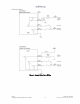
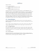
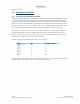
Using the above set-up a vehicle can be enabled or disabled by clearing (enabled) or setting
(disabled) output 0 via PEG Scripts, Real-Time PEG Actions or SMS messages.
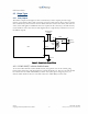
4.3.2 External vs. Internal Power Switch
This output allows the LMU to switch between power sources when certain conditions are
met (e.g. low power on the currently selected supply). If this output is set then the LMU will
use its internal battery as its power supply. If this output is cleared, the LMU will use the
external power supply.
By default, this output is cleared so the LMU will operate off external power.
4.3.3 Enable / Disable Battery Charging
This output allows the LMU to enable or disable the charging of its internal battery. If this
output is set then the LMU will stop charging the internal battery. If this output is cleared
the LMU will charge the internal battery.
By default, this output is cleared (i.e. battery charging enabled)
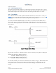
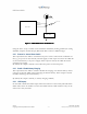
4.3.4 LED Outputs
On the LMU-1000™ the LED outputs mirror the behavior of the Comm and GPS Status
LEDs. These allow an installer to remote the LEDs from the LMU-1000™ so they can be
observed to verify an install.
Starter Relay
Key Switch
LMU-1000
BLUE
GREEN
Cut wire
Figure 4 - LMU-1000™ Vehicle Disable Feature