USAT USATCORP.COM Contact USATCORP.
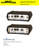
Vanguard Cellular Data Modem & IP Router Series User Manual 001-7200-100 Revision 0; June 2011
Copyright Notice ©2011 CalAmp. All Rights Reserved. CalAmp reserves the right to modify the equipment, its specification or this manual without prior notice, in the interest of improving performance, reliability, or servicing. At the time of publication all data is correct for the operation of the equipment at the voltage and/or temperature referred to. Performance data indicates typical values related to the particular product.
Revision History 2011 June Initial Release 3
Table of Contents 1 Product Overview ................................................................................................................................................................ 6 1.1 Module Identification ................................................................................................................................................. 6 1.2 Features and Benefits................................................................................................................
3.10.1 Status ............................................................................................................................................................... 58 3.10.2 Settings ............................................................................................................................................................ 60 3.10.3 Labels .................................................................................................................................................
1 PRODUCT OVERVIEW The Vanguard Series from CalAmp is the ideal solution for a wide range of cellular data network serial and Ethernet connectivity requirements. CDMA models feature EV-DO Rev A speeds with data rates up to 3.1 Mbps downlink and 1.8 Mbps uplink and are backward compatible to EV-DO Rev 0 and 1xRTT dependant on carrier service availability. This occurs automatically to the level of service available.
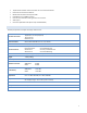
1.3 TCP/IP Packet assembler and dis-assembler for serial connected devices Inbound IP termination with Static IP Modem Domain Names with Dynamic DNS Embedded Linux on ARM 9 processor Internet access and web browsing via Ethernet connector VPN support On-board 1.8/3V SIM socket (Active only for GSM Models) GENERAL SPECIFICATIONS Product specifications are subject to change without notice.
1.4 MECHANICAL SPECIFICATIONS The following section describes in detail the exterior dimensions of the 882 GSM Series modems and how to utilize the mounting flanges to secure the modem to any surface, which can be drilled for such a purpose. The drawings may be used as layout reference, but it is advised that a physical comparison be made to the modem before proceeding with the mounting process. Figure 3 Vanguard Mechanical Drawing 1.
Table 2 - Vanguard Accessories Vanguard Accessories ACC-ANTN-RBD 4” Rubber Duck Antenna ACC-ANTN-MAG 3” Mag Mount Antenna ACC-PWSP-ML2 110 VAC Input Power ACC-PWDC-MLX DC Power Cable ACC-CABL-SER DB-9 Serial Cable ACC-CABL-ETH 7’ Ethernet cable 9
1.6 EXTERNAL CONNECTORS This section describes the external connectors for the Vanguard modem. Figure 4 shows the front panel connections for Standard (Fixed) models. Figure 5 shows the front panel connections for Mobile models with GPS and WiFi. Figure 6 shows the rear panel for all models.
Table 3 describes these connections.
Table 3 – External Connectors Panel Indicator Connection Description COM RS-232 Serial to IP conversion use ANT SMA Primary RF Antenna AUX (Figure 4) SMA Cellular Diversity or Cellular/GPS combination antenna AUX (Figure 5) RP-SMA Wi-Fi antenna GPS SMA GPS Antenna DIV SMA Cellular Diversity Antenna LAN 1, LAN 2 RJ-45 Interface for Ethernet connection to devices SIM/SVC USB Mini Available for CalAmp Support Use Only PWR Jack Molex 43025-0400; Power – bottom pins; I/O – top pins S
antenna, with an average gain >-5dBi, if using the GPS functionality. If both RX diversity and GPS are required, install a Cellular/GPS combo antenna. This device is configured with default settings and is ready to be configured via HTML. Some configurations may be set using AT commands. Refer to Section XX for AT Commands using the Serial Port. 1.8 RS-232 SERIAL PORT INTEGRATION PARAMETERS Table 5 provides the serial cable design information to integrate the Vanguard modem into your system.
2 GETTING STARTED 2.1 PACKAGE CONTENTS 2.2 2.3 Vanguard Modem Power Cable Information Card DEVICE CONNECTIONS 1. (GSM Users) Insert the SIM card into the SIM/SVC slot as shown. 2. 3. 4. Connect an antenna to the ANT connector on the front panel of the Vanguard modem. Connect an Ethernet cable into the LAN 1 port and plug the other end into the network port of your PC. Connect the Power Adapter to the modem PWR port and plug into a proper AC power socket.
Figure 8 LAN Configuration Screens 2.4 CELLULAR CONNECTIONS Before you begin, you will need an active Cellular account with the carrier of your choice. 2.4.1 GSM USERS Insert the SIM card with the gold side up into the SIM/SVC slot in the rear of the device. Push the card completely into the slot until it clicks in place. If you have already powered your device, you will need to cycle power to register the SIM for proper operation. 2.4.2 CDMA USERS Refer to Section 3.
3 VANGUARD WEB INTERFACE Start your web browser and enter 192.168.1.50 in the address bar. A login screen should appear. Enter the User Name: admin and the Password: password and click OK to log into the modem’s Home Page. Vanguard Web interface is divided into two sections. On the left is the main navigation panel (shown in Figures 9-10). On the right is the content area for the desired page (shown in Figures 11-12). Figure 9 LAN CDMA Main Navigation Panel 3.
Figure 11: Vanguard CDMA Unit Status Window 17
Figure 12: Vanguard GSM Unit Status 18
LAN IP Displays LAN side static IP information for this device (the modem). Note: Once this IP address has been changed and saved, the browser connection to the device will be lost. To continue configuration, please connect to the (new) IP address / the address that has been entered and saved. Subnet Mask Displays the LAN side subnet mask for the modem MAC Address Media Access Control Address. Every Ethernet device (i.e.
PPP IP Address Displays the current IP address of the Modem on the cellular network. This address, if public, should be reachable. 10.X.X.X subnets are not routable from the Internet PPP Subnet Mask Usually set to 255.255.255.
Service Type Determines the type of network your device has connected to; GPRS, EDGE, UMTS, HSDPA, CDMA 1xRTT, EVDO Rev0 or RevA. ESN The Electronic Serial Number is only applicable for the CDMA product line, carrier specific (Alltel, Verizon, Sprint, etc). MDN/MTN The actual phone number of the device as supplied by the carrier. When the unit is successfully provisioned, the phone number for the user account will be displayed.
Figure 13: Vanguard CDMA Unit Status – Basic Settings Unit ID 3.2 ID This identification number serves to distinguish this unit from other units in the network. It is at the same time the TAIP identification for GPS reporting and serves as the 'syslocation' for the SNMP facility. SIM SETTINGS (GSM MODELS ONLY) One of the key features of GSM is the Subscriber Identity Module (SIM), commonly known as a SIM card. The SIM is a detachable smart card containing the user's subscription information.
Change the Disable PIN setting from Yes (shown in Figure 14) to NO. Enter your carrier provided PIN into the Current PIN field. Click SAVE to access the PIN Security Settings (shown in Figure 15). Figure 15 PIN ACCEPTED Security Enabled The PIN security feature is now enabled. PIN STATUS shows that the PIN has been ACCEPTED. Each time modem power is cycled, the proper PIN will need to be entered in order for the modem to dial out.
Figure 16 SIM Settings for PIN Required At this point the user has 3 attempts to enter the correct PIN. If the correct PIN is not entered after 3 attempts, an unlock code or PIN Unblocking Key (PUK) from the service provider will be required before the SIM card is usable again. Figure 17 shows the SIM settings after an incorrect PIN has been entered. Figure 17 SIM PIN Rejected Figure 18 shows the SIM page requiring the unlock code to be entered.
3.3 PROVISIONING (CDMA MODELS ONLY) When a CDMA modem is powered up for the first time, most of the provisioning information is blank or has information that needs to be changed. The device is usually shipped with the radio ready to be provisioned on a cellular carrier’s network. Features called Over-The-Air Service Provisioning (OTASP) and Internet Over-The-Air (IOTA) are supported, which allow the cellular providers to program the modem with specific information to activate the account.
If the auto-provisioning fails, and OMA-DM manual provisioning fails, and your outside the Sprint network, follow the manual-entry activation steps below. Manual-Entry Activation If provisioning must occur in a roaming area, make sure to have a medium to strong signal strength because manual-entry activation will be required. Select Provisioning from the side menu bar. Input the MDN/MTN and MSID/IMSI (MIN) given by your provider. Put in the unlock code given by your provider.
The Electronic Serial Number is only applicable for the CDMA product line, carrier specific (Alltel, Verizon, Sprint, etc). This number is used to set up the user account with the cellular provider. MDN/MTN The actual phone number of the device as supplied by the carrier. When the unit is successfully provisioned, the phone number for the user account will be displayed.
Click the Write MDN/MSID button when the required information has been entered. Enable/Disable OMA-DM Activation This section will only be displayed for units which are capable of automatic (OMA-DM) provisioning. You may choose to enable or disable the automatic provisioning and save your desired setting. If enabled, and the unit is not provisioned (activated), each time at power-on (only) the unit will attempt an auto-activation.
Figure 20: Vanguard CDMA Provisioning – Advanced Settings Profile Settings Profile Enable This field indicates if the profile is enabled. It is possible to enable both profiles. Whether to enable 1 or both profiles should be based on information from the provider NAI Network Address ID. This field should be set the NAI supplied by the provider. Home IP Address This parameter should be set to the Home IP Address supplied by the provider.
MN-HA SPI This parameter should be set to the MN-HA SPI setting supplied by the provider. This is a numeric setting. HA Secret This parameter should be set to the Home Agent Secret (password) supplied by the provider. AAA Secret This parameter should be set to the AAA Shared Secret (password) supplied by the provider. Rev Tunnel Reverse Tunneling may be enabled or disabled, as specified by the provider.
Figure 21: Vanguard CDMA Cell Connection – Dial Settings Figure 22: Vanguard GSM Cell Connection – Dial Settings 31
Dial Settings Auto Connect When set to Enable, will allow the modem to automatically dial the connection when the modem is powered. When set to Disable, the modem will not automatically dial the connection to the cellular provider and will not attempt to automatically re-connect when the connection has dropped. Dial Number The phone number used to initiate a data connection to the cellular provider via PPP. The default dial number is #777. User Sets the username required by the cellular provider.
Figure 23: Vanguard Cell Connection – System Monitor Periodic Reset Timer Periodic Reset Type Sets the Periodic Modem Reset timer to an Interval time, a Scheduled day, or disables it. Interval Length Sets the Periodic Modem Reset time from 15 to 65,535 minutes. The Periodic Reset is disabled when set to 0. Default is set to 4320 min. (approximately 3 days) Scheduled Time Sets the Periodic Modem Reset to occur at the specified time. Select the days of week desired or 'All' for everyday.
Destination Address User may enter an accessible IP address or URL that will respond to a ping command. Secondary Address User may enter an accessible IP address or URL that will respond to a ping command. This address will be used if the entered number of consecutive ping failures using the first address is reached. Periodic Ping Timer User may enter an interval in increments of 10 seconds. The modem will ping the destination at that interval. Enter 0 to disable this feature.
The number of corrupted TCP and UDP packets received by the modem that were meant to be transmitted on the cell network. Tx Packets Dropped The number of TCP and UDP packets received by the modem for transmit to the cell network that were not accepted. This may occur due to memory or throughput problems. Press Clear to reset the totals to 0. These totals are NOT cleared by a modem reboot. 3.4.3 DYNAMIC DNS Select Cell Connections from the left navigation pane.
The username used when setting up the account. Used to login to the Dynamic DNS service. User Password The password associated with the username account. Hostname The hostname identified to the Dynamic DNS service. For example http:/test.myserver.com. Update Interval Sets the interval, in minutes (0 to 65,535), the modem will update the Dynamic DNS server of its carrier assigned IP address. It is recommended to set this interval as long as necessary.
Figure 25: Vanguard LAN Settings Window 37
LAN Settings Ethernet IP Address This sets the IP address of this device and is the address used to access the configuration pages. If the IP address changes you will have to re-enter the new IP address in your browser to access the configuration pages. The default IP is 192.168.1.50 and should be changed for security purposes.
DHCP end range DHCP server ending IP address. The maximum usable number is 253 DHCP Lease Time Sets the duration, in seconds, the connected device is allowed to keep the assigned IP address. In many cases it is possible for the device to receive the same IP address after the lease time expires.
Enable or disable RADIUS authentication for webpage access Server IP Address The IP address of the RADIUS server Server Port The port of the server Server Secret Sets the secret to use with the server Confim Secret Re-type the Server Secret to confirm the correct spelling Timeout Specify how many seconds to wait before a retry Retries Specify how many times to retry authenticating with the server before giving up Press Save to keep the currently displayed value for each parameter.
Figure 26: Vanguard LAN Settings – MAC Filtering MAC Filtering MAC Filtering Radio button selection to Enable/Disable MAC filtering Allowed MAC Address Enter the MAC address for a device to be allowed on the network. Comment Here a name can be inserted describing the device using the allowed MAC address. Clear Press to remove the MAC address from the list of allowed addresses. Press SAVE/CANCEL to implement or cancel changes. 3.
Figure 27: Vanguard Router – Port Forwarding DMZ Support DMZ is a host on the internal network that has all ports exposed, except those ports forwarded otherwise. DMZ Radio button selection to Enable/Disable; Select Enable to allow the modem to use DMZ routes using the address set in the Destination IP Address. Select Disable to shut down the DMZ functionality. Friendly IP Address Optionally restricts DMZ access to only the specified IP address. If set to "0.0.0.
Port Forwarding Radio button selection to Enable/Disable. Select Enable to allow the modem to use the Port Forwarding routes described in the IP mapping table. Select Disable to shut down the Port Forwarding functionality. The SAVE button must be pressed for changes to take effect. Port Forwarding Configuration Map Name Sets the Map Name for the IP mapping table at the bottom of the screen. The Map Name can be up to ten characters in length.
Figure 28: Vanguard Router – Static Routes Static Routes Route Name Sets the alphanumeric identifier of the static route in the Static Route Table Destination IP Address Sets the IP address of the destination network IP Subnet Mask Sets the subnet mask of the destination network Gateway Sets ppp (this router's wireless internet connection), pptp (VPN), GRE Tunnel, or the local network IP address for the gateway to the destination network Gateway IP Address This is only used if local IP a
3.7.1 PPTP The Point-to-Point Tunneling Protocol (PPTP) is a method for implementing virtual private networks (VPN). Figure 29: Vanguard VPN – PPTP PPTP Client Configuration PPTP Client Selecting Enable will allow the PPTP functionality. Selecting Disable will shut off PPTP functionality Set Default Route to PPTP Selecting Enable will route all IP traffic through the PPTP network.
Username The username required by the VPN server Password The password, associated with the username, required by the VPN server PPTP Server Configuration PPTP Server Selecting Enable starts the VPN server, and selecting Disable stops it Server Local IP The IP address that clients will use to communicate with the server after they connect Client IP Range The pool of IP addresses assigned to clients Protocols Allowed Selecting a protocol will instruct the VPN server to accept clients w
Figure 30: Vanguard VPN – IPSec IPsec Support IPsec Selecting Enable will launch the IPsec process and start all enabled tunnels. Selecting Disable will stop all tunnels and shutdown the IPsec process. Note that all enabled tunnels will be launched automatically when the unit connects to the cellular carrier.
NAT Mode Determines how packets are addressed. Selecting Bypass will allow packets coming from Local Subnet addresses through the NAT firewall unchanged. This may be sufficient when traffic only travels from Local Subnet to Remote Subnet. (LAN Settings > Bind to Eth IP may need to be enabled to make sure that packets generated by Vanguard services appear to originate from a Local Subnet address.) NAT changes the source address to match the Status > PPP IP Address.
Phase 2 Encryption Use AES-128, AES-256 or 3DES encryption. Phase 2 Authentication Use MD5 or SHA1 hashing. Phase 2 Lifetime How long a particular instance of a connection should last, from successful negotiation to expiry. Pre-shared Key: Predetermined key known to both the local unit and the remote side prior to establishing the tunnel. Negotiation Mode Choose Normal to allow IPsec to negotiate some connection parameters.
Figure 31: Vanguard VPN – GRE GRE Tunnel Configuration 3.8 Local IP Address The local IP address associated with the tunnel Remote IP Address The remote IP address associated with the tunnel Tunnel IP Address The IP address assigned to the tunnel interface. SERIAL From the main navigation pane, select Serial for access to both external and internal serial port configuration screens. 3.8.
Figure 32: Vanguard Serial – External Serial External Serial Port Configuration Serial Port When enabled, the external serial port PAD function can be used. When disabled, no PAD function is available, and the port is left free, for use by an ODP application. Show Version on Boot When enabled, the router model number and firmware version are transmitted out the serial port at router boot. Additionally, "OK" is transmitted when router is ready to receive data and when PPP connection is made.
Baud Rate Sets the baud rate of the serial port. Settings may range from 300 to 115,200 bits per second. The default baud rate is 115,200 bps. Inter Character Timeout Sets the Inter Character Timeout from 1 to 65,535 ms. DTR Defines the Data Terminal Ready behavior. Refer to Table XX for DTR descriptions. Table 7 – DTR Descriptions AT&D0 Ignore DTR.
DCD The DCD parameter determines how the modem controls the state of the Carrier Detect circuit and the amber DCD LED on the front panel. The default value is Connect On. ― Always On: DCD is always on. ― Connect On: DCD is on when connected to a remote host. ― Always Off: DCD is always off. RI The RI parameter determines how the modem controls the state of the Ring Indicator circuit. The default value is Always Off. ― Always On: RI is always on. ― Connect On: RI tracks incoming ring pulse.
New Client: If a different client attempts to connect, it will be successful and the current client will be forcibly disconnected, without any warning. Otherwise, the current client remains connected indefinitely. Timeout: A new client will be accepted only after a specified timeout. The duration of the timeout is specified by the Inactivity timeout, or the Hard timeout, or a combination of both. The default value is New Client.
Time in seconds between keep alive cycles. A keep alive cycle will consist of one or more keep alive probes separated by the keep alive interval. TCP Client Keep Alive Probes Number of keep alive packets that must fail before connection is considered closed TCP Client Keep Alive Intvl Time in seconds after which a keep alive packet is considered to be failed (if not acknowledged).
3.
Figure 34: Vanguard Diagnosics – SNMP SNMP Configuration SNMP Selecting Enable will allow the SNMP functionality. Selecting Disable will shut off SNMP functionality. Version With SNMP Enabled, select the corresponding version that matches the SNMP Manager.
SNMP v3 User Name The user name for secure access to the Management Information Bases (MIBs) observing v3 standard Password The corresponding user password for accessing the Management Information Bases (MIBs) including writable objects Authentication Selecting the authentication method for accessing the Management Information Bases (MIBs) Traps Traps Selecting Enable will allow the active trap events to be reported to the defined server(s).
Version Displays the modem firmware version currently loaded in the unit Kernel Date Displays the date of the operating system kernel the unit is running Logging Settings Auto-Logging Selecting Enable and pressing Save will enable the logging capability which saves periodic and event driven logs to permanent memory. Technical Services personnel may find such logs useful in analyzing field issues. Selecting Disable and pressing Save will disable the logging capability. This is the default setting.
Figure 36: Vanguard I/O Settings – Status Device Input Status Main Voltage Displays current voltage applied to the unit, in Volts Modem Temperature Displays temperature of the Wireless Modem, in Celsius Analog Input Status Analog Input 1, Analog Input 2 Displays voltage of the specified analog input, in Volts.
Displays the status of the specified output as open or closed 3.10.2 SETTINGS Status Monitoring is provided via NMEA-based protocol. The Vanguard I/O subsystem operates according to a manager/agent model. The PC-hosted manager sends requests to the Vanguard I/O agent, which performs the required actions. The Vanguard agent reports alarms to the PC-hosted manager.
Unit ID The Unit Name to be included in the NMEA message payload. Source Identification The Unit's IP address that will be included in the NMEA message payload Triggers – Device Cell Temperature and thresholds Enable or disable NMEA alarm and notification when temperature goes out of range. Triggers – Analog Input Analog Input and thresholds (1 or 2) Enable or disable NMEA alarm and notification when an analog input goes out of range.
Figure 38: Vanguard I/O Settings – Labels 3.11 FIRMWARE UPDATE When newer versions of the modem firmware become available, the user can download the proper file from the CalAmp web site and manually update the unit by uploading the new firmware. The update file name is: ― upgradeevdo.tar.gz for the Vanguard EVDO modem.
Figure 39: Vanguard Firmware Update Current Firmware Information Version Displays the modem firmware version currently loaded in the unit. Kernel Date Displays the date of the operating system kernel the unit is running Upload New Firmware File Enter the update file name or you may use the browse button to locate the file from your hard drive. Updates can be done if Remote Administration is enabled. Progress Displays the update progress after the Save button has been pressed.
Upload Button After selecting the firmware configuration filename above, press the Upload button to begin the configuration loading process. Save Returns a link to the configuration file on the unit. Right-click the link and select "Save Target As..." to save the file. The link page refreshes after 15 seconds. It is recommended to use the specified filename to save the file. If multiple files need to be maintained, it is recommended to use directory paths to separate the files.
4 SERVICE AND SUPPORT Product Warranty, RMA and Contact Information CalAmp guarantees that every Vanguard Modem will be free from physical defects in material and workmanship for one (1) year from the date of purchase when used within the limits set forth in the Specifications section of this manual. The manufacturer's warranty statement is available in Appendix 1. If the product proves defective during the warranty period, contact CalAmp Customer Service to obtain a Return Material Authorization (RMA).
APPENDIX A – ABBREVIATIONS Abbreviation Description APN Access Point Name CSD Circuit Switched Data CTS Clear to Send DCD Data Carrier Detect DCE Data Communication Equipment DTE Data Terminal Equipment IMEI International Mobile Equipment Identity EDGE Enhanced Data rates for Global Evolution GPRS General Packet Radio Service GPS Global Positioning System GSM Global System for Mobile communication HSDPA High-Speed Downlink Packet Access LED Light Emitting Diode ME Mobile Equipme
APPENDIX B – WARRANTY STATEMENT CalAmp warrants to the original purchaser for use ("Buyer") that data telemetry products manufactured by Dataradio ("Products") are free from defects in material and workmanship and will conform to published technical specifications for a period of, except as noted below, one (1) year from the date of shipment to Buyer.