Contents Pre-Delivery and Installation Checklist....................................... 1 Planning the Best Location.......................................................... 2 Portable Spa Site Preparation...................................................... 4 In-Ground Spa Site Preparation................................................... 4 Getting the Spa Into Your Yard.................................................... 6 Electrical Requirements.........................................................
Pre-Delivery and Installation Checklist Most cities and counties require permits for exterior construction and electrical circuits. In addition, some communities have codes requiring residential barriers such as fencing and/or self-closing gates on property to prevent unsupervised access to the property by children under the age of 5. Your dealer can provide information on which permits may be required and how to obtain them prior to the delivery of your spa.
Planning the Best Location Safety first Do not place your spa within 10 feet (3 m) of overhead power lines. Make sure the spa is positioned so that access to the equipment compartment and all side panels will not be blocked. Be certain that your installation will meet all city and local safety codes and requirements. Consider how you will use your spa How you intend to use your spa will help you determine where you should position it.
Allow for service access Many people choose to install a decorative structure around their spa. If you are installing your spa with any type of structure on the outside, such as a gazebo, remember to allow access for service. It is always best to design special installations so that the spa can still be accessed. Outdoor equipment pack (in-ground spas only) The Designer Spa series requires an external equipment pack.
Portable Spa Site Preparation Your spa needs a solid and level foundation. The area that it sits on must be able to support the weight of the spa, with water and the occupants who use it. If the foundation is inadequate, it may shift or settle after the spa is in place, causing stress that could DAMAGE YOUR SPA SHELL AND FINISH. Note: Damage caused by inadequate or improper foundation support is not covered by the warranty.
• The spa must be properly back-filled with wet sand, underneath and on all four sides. • The final architecture must include permanent ground coverage within a 10 feet radius of the spa. • Never place any spa in a sealed area. Water must be able either to be absorbed into the surrounding area or channeled away. Water buildup under and/or around the spa, will cause the spa to float out of the ground.
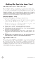
Getting the Spa Into Your Yard Check the Dimensions of Your New Spa The specification chart on page 26 lists your spa’s model and its dimension as it sits on the delivery cart. During delivery, the spa must remain on the delivery cart at all times. Compare the dimensions to the width of the gates, sidewalks, and doorways along the delivery route. It may be necessary for you to remove a gate or partially remove a fence in order to provide an unobstructed passageway to the installation location.
LTR20091024, Rev.
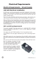
Electrical Requirements Electrical Requirements – US and Canada 240 Volt Electrical Installation All 240V spas must be permanently connected (hardwired) to the power supply. These instructions describe the only acceptable electrical wiring procedure. Spas wired in any other way will void your warranty and may result in serious injury. This is the only acceptable electrical wiring procedure. Spas wired in any other way will void your warranty. See the wiring diagram on page 11.
Portable Spas Spa Model All 240V spas (except 6300 control boxes requiring high amperage - see below) Spas with the 6300 control box (when high amperage is selected on circuit board) GFCI Required Wires Required One 50 amp GFCI Four #8 AWG copper wires One 60 amp GFCI Four #8 AWG copper wires One 50 amp GFCI Four #8 AWG copper wires SEE CONFIGURATION INSTRUCTIONS ON NEXT PAGE. Ultimate Fitness Spas F2400 spa with one 5.5 kW heater Service 1: One 60 F2400 and FP2500 spas amp GFCI with two 5.
Testing the GFCI Breaker Test the GFCI breaker prior to first use and periodically when the spa is powered. To test the GFCI breaker follow these instructions (spa should be operating): 1. Press the TEST button on the GFCI. The GFCI will trip and the spa will shut off. 2. Reset the GFCI breaker by switching the breaker to the full OFF position, wait a moment, then turn the breaker back on. The spa should have power again.
GFCI Wiring Diagram LTR20091024, Rev.
120 Volt Electrical Installation Always follow applicable local, state and federal codes and guidelines. Use only a dedicated electrical line with a 20-amp breaker. Cord-and-plug connections may not use a cord longer than 15 ft (4.6 m) and must be plugged into a dedicated 20-amp GFCI connection. Do not use extension cords! Always use a weatherproof-covered receptacle. Receptacle shall be located not less than 5 ft (1.5 m) from and not exceeding 10 ft (3.0 m) from the inside wall of the spa.
Electrical Installation -- Europe 230 Volt Electrical Installation All 230V spas must be permanently connected (hardwired) to the power supply. These instructions describe the only acceptable electrical wiring procedure. Spas wired in any other way will void your warranty and may result in serious injury. This is the only acceptable electrical wiring procedure. Spas wired in any other way will void your warranty. See the wiring diagram on page 15.
Portable Spas Spa Model All 230V spas (except 6205 control boxes requiring high amperage - see below) Spas with the 6300 control box (when high amperage is selected on circuit board) SEE CONFIGURATION INSTRUCTIONS ON NEXT PAGE. Ultimate Fitness Spas F2400 spas with one 5.5 kW heater FP2500 spa with one 5.
RCD Wiring Diagram LTR20091024, Rev.
Installing the In-Ground Shell 16 LTR20091024, Rev.
Equipment Pack Plumbing Connections (In-Ground Spas) The example shown below is typical for a system with two pumps with external heater and external filter. Designer Spa Specifications DIJ401 and DIJ405: Equipment pack weight = 250 lbs. DIJ407: Equipment pack weight = 300 lbs. 2.5 HP heat pump 4 HP swim pump Note: Equipment pack cannot exceed 15 feet from spa. LTR20091024, Rev.
18 LTR20091024, Rev.
In-Ground Plumbing Connections IMPORTANT! Always check local codes prior to any in-ground spa installation. Once the spa and equipment are properly located, you will want to lay out the plumbing run. Trenches should be deep and wide enough to allow all pipes to be buried below the frost line and should be in as straight a line from the spa to the equipment as possible. Check local code requirements for underground pipes. Always know what is under the ground before you dig anywhere.
NOTE: Once complete, water test the plumbing run for at least three days prior to covering any plumbing trenches and back-filling spa cavity completely. NOTE: Some local inspectors require pressure testing the plumbing lines. Although the spa is pressure tested at the factory, local inspectors may insist on pressure testing the plumbing run between the spa and equipment pack. Gate/Slice Valves The use of gate valves is recommended on all plumbing lines (both suction and return lines).
Air Venturi: 1/2” line that is plumbed 18” above the spa’s water level. Topside Control Panel and Temp Sensor: 1” line that connects to the bottom of the control box located on the equipment pack. Electrical and Electronic Connection Remote Equipment Topside Control Panel The next few steps to complete the installation should be performed along with installation of the temperature sensor and 12V spa light wiring (if applicable). All of these components are generally installed using the same conduit. 1.
NOTE: Circuit board programming will not allow spa operation without both the temperature and high limit sensors being properly connected to the circuit board. 7. Once topside panel operation is verified. Turn off power, disconnect the extension loom from the circuit board and GENTLY route through conduit to complete installation. NOTE: This loom and its connector are not meant to withstand heavy pulling.
Light niche and any metallic items in a 5’ (152 cm) radius must be properly bonded with #8 AWG grounding wire. 1. Connect rigid conduit to the 3/4” hub located at the back of the light niche and run to a water resistant junction box (or for 12 volt models to a low voltage transformer) no further than 25’ (7.6m). Remember this is a water cooled light, so the conduit and all connections must be leakproof. 2.
24 LTR20091024, Rev.
Pouring the In-Ground Spa Deck It is recommended that all electrical hook ups and all plumbing be completed before pouring the concrete. Make certain all electrical inspections on lights, bonding and all other electrical work have been completed and checked off by the local inspectors prior to proceeding with your concrete or finish work. It is a good idea to run the spa for at least 24 hours before pouring the concrete to insure there are no leaks.
Spa Technical Specifications All sizes on this chart represent outside dimensions. Due to our continuous improvements, specifications, size and pricing are subject to change without prior notice. Avalon Series Width Length Depth Gallons Dry Weight Filled Weight A515 84" 64" 32" 325 600 Lbs. 3307 Lbs. A526 84" 64" 32" 325 600 Lbs. 3307 Lbs. A534 84" 64" 32" 325 600 Lbs. 3307 Lbs. A726B 84” 84” 39½” 425 850 Lbs. 4390 Lbs. A726L 84” 84” 39½” 425 850 Lbs. 4390 Lbs.
Classic Series Width Length Depth Gallons Dry Weight Filled Weight CL-25 64” 84” 32” 125 535 Lbs. 1576 Lbs. CP-36 84” 84” 39½” 425 850 Lbs. 4390 Lbs. CT-36 84” 84” 39½” 425 850 Lbs. 4390 Lbs. CP-50 84” 84” 39½” 425 850 Lbs. 4390 Lbs. CT-50 84” 84” 39½” 425 850 Lbs. 4390 Lbs. CT-64 84” 84” 39½” 425 850 Lbs. 4390 Lbs. CP-65 84” 84” 39½” 425 850 Lbs. 4390 Lbs. CV-35 93” 84” 39½” 450 900 Lbs. 4648 Lbs. CA-65 93” 93” 39½” 450 900 Lbs. 4648 Lbs.
Family II Series Width Length Depth Gallons Dry Weight Filled Weight F515R 78" Round 36" 300 350 Lbs. 2849 Lbs. F518S 43” 83” 32” 100 250 Lbs. 1083 Lbs. F520B 54" 78" 31" 125 350 Lbs. 1391 Lbs. F730B 84" 84" 35” 425 800 Lbs. 4340 Lbs. F730L 84" 84" 35" 425 800 Lbs. 4340 Lbs. F732B 84" 84" 35" 425 800 Lbs. 4340 Lbs. F732L 84" 84" 35" 425 800 Lbs. 4340 Lbs. F745B 84" 84" 35" 425 800 Lbs. 4340 Lbs. F745L 84" 84" 35" 425 800 Lbs. 4340 Lbs.
Ultimate Fitness and Fitness Pro Series Width Length Depth Gallons Dry Weight Filled Weight F854 93” 93” 52” 650 1500 Lbs. 6914 Lbs. F1257 96” 144” 52” 2000 1600 Lbs. 18260 Lbs. FP1455 96” 174” 52” 2500 2000 Lbs. 22825 Lbs. FP1755 96” 203” 52” 2500 2000 Lbs. 22825 Lbs. F2400 96” 170” 52” 2000 1800 Lbs. 18460 Lbs. FP2500 96” 206” 51” 2500 2000 Lbs. 22825 Lbs. FP4700 96” 202” 52” 2000 / 285 2950 Lbs. 21985 Lbs.
LMS Customer Service Department 1462 East Ninth Street Pomona, CA 91766 Toll Free: 1-800-CAL-SPAS Fax: 1-909-629-3890 www.calspas.com LTR20091024, Rev.