
Specifications
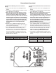


– 33 –
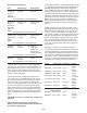
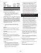
MULTIPLEXED VOLTAGE CHART
RESISTOR
VALUE RESISTOR ID
SWITCH
CLOSED
OHMS IN
CIRCUIT VOLTS DC
1000 RS1 RS1,2,3,4 0 0
2000 RS2 RS2,3,4 1000 0.30
4020 RS3 RS1,3,4 2000 0.55
8060 RS4 RS3,4 3000 0.76
RS1,2,4 4020 0.95
RS2,4 5020 1.10
RS1,4 6020 1.24
RS4 7020 1.36
RS1,2,3 8060 1.47
RS2,3 9060 1.57
RS1,3 10060 1.65
RS3 11060 1.73
RS1,2 12080 1.80
RS2 13080 1.87
RS1 14080 1.92
NONE 15080 1.98
UNPLUGGED NA 3.30
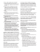
IN-3 JUMPER RS-04 MIXED AIR TEMP
RE-56 RS-03 SAFETY CKT STATUS
RE-09
TO
GND RS-02 FLAME FAILURE
SW-72 RS-01 100% OA or 100% OUTPUT
IN-4 RE-27 RS-04 BURNER STATUS
RE-65 RS-03 FAN STATUS
RE-12
TO
GND RS-02 CLOGGED FILTER
SW-09 RS-01
= 1.36
= 1.73
= 1.87
= 1.92
= 1.36
= 1.73
= 1.87
= 1.92AUXILIARY UNIT ENABLE
MULTIPLEXED VOLTAGE
VALUES
CHECK ALL TERMINAL CONNECTIONS FOR TIGHTNESS
The DC voltage is to be checked at the UC-01 board
With the Fan Enabled:
When the fan status relay (RE-65) is energized, the
contacts will close and the VDC at IN-4 & GND will be
1.73.
With the Fan and Burner Enabled:
When the safety circuit relay (RE-56) is energized,
the contacts will close and the VDC at IN-3 & GND
will be 1.73. When the burner status relay (RE-27) is
energized, the contacts will close and the VDC at IN-4
& GND will be 0.76.