
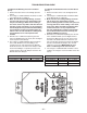
Specifications


– 38 –
B Section
small Pounds
pulley Pounds Force for
diameter Belt Force for 1
1
/
2
times
range in Manufacturer Normal Normal
Inches & Type Belt Tension Tension
3.4-4.2 Gates Hi-Power 4.4 6.6
4.4-4.6 Gates Hi-Power 4.9 7.4
5.8-8.6 Gates Hi-Power 5.8 8.7
Note: For recommendation of other types of belts,
consult respective manufacturers.
E. Optional Coils And Related Items
1. Coils – Coil surfaces must be kept clean of dirt
and lint in order to operate at rated effi ciency.
Coils should be inspected on a regular basis and
cleaned as required.
CAUTION: Solutions used to clean coils must
not be corrosive to metals or materials
used in the manufacturer of this equipment. If
cleaning solutions are applied through means
of high pressure spray, care must be taken to
avoid damaging the coil fins. Always follow the
manufacturer’s warnings and directions for the
coil cleaner you are using.
2. Condensate Drain Pan – Periodically fl ush the
condensate pan and drain system with a water
hose.
F. Gaskets
Gaskets are used on doors, inspection covers, some
fi lter racks, and some outdoor air dampers. Inspect
gaskets periodically and repair or replace as required.
G. Caulking
Inspect unit and add caulking as required.
H. Casing
Periodic cleaning of the casing is recommended to
remove dirt, grease and any corrosive substances that
may harm the fi nish. Rusted or corroded spots should
be cleaned and repainted.
I. Support Means
Inspect the entire unit and burner support means to be
sure everything is fi rmly in place.
J. Heater
1. At least a yearly inspection is recommended
for heating installations and more frequently for
process applications in year-round operation. Your
own experience is the best guide in determining
frequency of inspection, but as a minimum the
following procedure should be followed:
a. Shut the system down totally, disconnecting or
locking out power supply so there can be no
accidental start-up during inspection.
b. Inspect the burner carefully, including upstream
and downstream sides of mixing plates as well
as burner body face. Note that complete burner
assembly may have to be removed for proper
inspection and cleaning. Any accumulation of
scale or foreign material on either side of the
mixing plates should be removed with a wire
brush. Check visually that no holes in the mixing
plates are blocked. If any burner ports are
plugged (even partially) clear them with a piece
of wire. See Maintenance of Gas Ports.
WARNING: Do not enlarge burner ports or
performance may be drastically affected.
If any mixing plates are loose or missing fasteners,
tighten/replace as necessary. Always use zinc
plated or stainless fasteners. The mixing plates
on the burner may display “hairline” cracks.
These cracks are normal, and caused by
thermal stresses occurring during combustion.
The presence of these “hairline” cracks in no
signifi cant way affects the combustion effi ciency
or performance of the heater. Should a large
opening develop, it may cause diffi culties in cross
ignition of fl ame across the face of the burner. If
this does occur, the specifi c mixing plate or plates
involved must be replaced.
c. Put system back into operation and view burner
while cycling through full fi ring range. This will
give a visual check for blocked burner ports.
2. Inspect the fl ame rod and ignition electrode for dirt
and moisture. Wipe off if necessary. Examine for
any evidence of premature arcing. If in doubt, check
continuity of fl ame rod to be sure it is not grounding
out. Replace if required.
The porcelain on the ignition electrode must be
intact - not cracked. The spark gap should be 1/8 of
an inch on Mestek burners.
3.
Replace all access panels which have been removed
and operate the unit for a test period. Check for
normal response and function of all controls.
4. Check all gas piping for possible leaks using a soap
bubble solution.
5. Inspect the support means to be sure that
everything is fi rmly anchored in place.