
Specifications


Catalog 1114-1 SmartSource 2-Stage Water Source Heat Pumps Page 33 of 76
Unit Selection
Achieving optimal performance with water source heat
pump systems requires both accurate system design and
proper equipment selection. Use a building load program to
determine the heating and cooling loads of each zone prior
to making equipment selections. With this information, the
Daikin McQuay SelectTools™ software selection program
for Water Source Heat Pumps can be used to provide fast,
accurate and complete selections of all water source heat
pump products. SelectTools software is available by con-
tacting your local Daikin McQuay Representative.
While it is recommend that you use SelectTools software
for all unit selections, manual selections can be accom-
plished using the same zone load information and the
capacity tables available in this catalog.
Boiler/Tower (Water Loop) Application:
The following example illustrates a typical selection for a
unit in a boiler/tower system for a commercial building.
The load in this zone requires 41,099 BTUH of total cool-
ing, 30,327 BTUH of sensible cooling and 37,758 BTUH
of total heating. The entering water temperatures for the
design conditions are 90°F for cooling and 70°F for heat-
ing. The return air temperature is 80°F dry bulb with 67°F
wet bulb and 70°F for heating.
Zone Requirement:
Total Cooling Load = 41,099 BTUH
Sensible Cooling Load = 30,327 BTUH
Heating Load = 37,758 BTUH
Design Air Flow = 1,200 CFM
Return Air - Cooling = 80ºF DB/67ºF WB
Return Air - Heating = 70ºF DB
Water Flow (Based on Cooling) = 10.5 GPM
Since a Model GT *038 at full-load performance produces
approximately 38,500 total cooling and 27,900 BTUH sen-
sible cooling capacity, it is not sufcient for this zone and a
model GT *044 should be considered.
Selection:
Model ..................................................................... GT *044
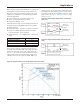
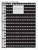
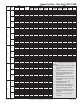
After making the preliminary selection (GT*044 – Full
Load), enter the performance from the tables on page 42
& page 43 ) at the design conditions and read Total Cool-
ing, Sensible Cooling, and Heating Capacity at 10.5 GPM:
Total Cooling Capacity = 44,000 BTUH
Sensible Cooling Capacity = 31,900 BTUH
Heating Capacity = 51,500 BTUH
Note: The above performances are based on 1,400 CFM;
therefore, the capacities need to be adjusted to
reect the unit performance at the zone required
CFM.
Applications
Determine the air ow correction factors from the table,
"Air Flow Correction Factors – Full Load" on page 51.
For this example use Air Flow Setting #2 (1225 CFM):
Corrected Total Cooling = 44,000 × 0.988 = 43,472 BTUH
Corrected Sensible Cooling = 31,900 × 0.954 = 30,433 BTUH
Corrected Total Heating = 51,500 × 0.991 = 51,037 BTUH
Compare the corrected Total Cooling, Corrected Sensible
Cooling, and the Corrected Total Heating gures to the
Zone requirements. This selection meets the requirements.
Next, determine the power correction factors using the
table, "Air Flow Correction Factors – Full Load" on page
51 using Air Flow Setting #2 (1225 CFM):
Corrected Cooling Input Power = 2.908 × 0.985 = 2.864 kW
Corrected Heating Input Power = 3.040 × 0.998 = 3.034 kW
The resulting efciencies can be determined using the cor-
rected capacities and input power:
EER = Cooling Capacity (BTUH) ÷ Input Power (Watts)
EER = 43,472 BTUH ÷ (2.864 kW × 1000) = 15.2
COP = Heating Capacity (Watts) ÷ Input Power (Watts)
COP = (51,037 BTUH ÷ 3.412) ÷ (3.034 kW × 1000) =
4.93
Geothermal (Ground Loop) Application:
The following example illustrates the same zone in a geo-
thermal application.
The space requirements for the zone are the same as the
previous example – 41,099 BTUH of total cooling and
30,327 BTUH of sensible cooling and 37,758 BTUH of
heating. Geothermal loop software programs are available
to help determine the size of the loop eld based on:
• Desired entering water temperatures for the system.
• Specic loop eld design criteria based on acreage
available, loop eld spacing, vertical bore depth, piping
selected, ow rates, circulated heat transfer uid, and
local formation geology for the loop which produces
specic min./max loop temperatures for the unit
selection.
Entering uid temperatures for geothermal systems can be
as high as 110ºF and as low as 20ºF. Design entering uid
temperatures for heating and cooling are selected by the
design engineer based on building loads, ground tempera-
tures, and soil conditions. Typical design entering uid
temperatures are 90°F for cooling (summer) and 45°F for
heating (winter). As a rule of thumb, the design entering
uid temperature for cooling is 10°F below the maximum
outdoor air temperature, and the design entering uid tem-
perature for heating is 40°F above the minimum outdoor air
temperature. Water ow rates are typically 2.5 to 3.0 GPM
per ton and the use of antifreeze is recommended in most
northern applications.