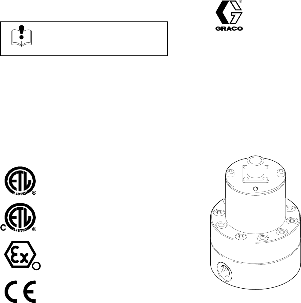
Parts INSTRUCTIONS-PART LIST 308778 Contents This manual contains important warnings and information. READ AND KEEP FOR REFERENCE. Rev. C Supersedes B First choice when quality counts. INSTRUCTIONS G3000 Volumetric Fluid Flow Meter 4000 psi (28 MPa, 276 bar) Maximum Working Fluid Pressure Part No. 239716 0.02 to 1.0 gpm (75 to 3800 cc/min.) Flow Range Recognized Component Conforms to ANSI/UL standard 2279 Certified to CAN/CSA 22.2 No. E79–11–95 EExia II A T4 D 98D.
Table of Contents Warnings . . . . . . . . . . . . . . . . . . . . . . . . . . . . . . . . . . . . . 3 Installation . . . . . . . . . . . . . . . . . . . . . . . . . . . . . . . . . . . . . 4 Operation . . . . . . . . . . . . . . . . . . . . . . . . . . . . . . . . . . . . . 6 Troubleshooting . . . . . . . . . . . . . . . . . . . . . . . . . . . . . . . . 7 Maintenance . . . . . . . . . . . . . . . . . . . . . . . . . . . . . . . . . . . 9 Flow Meter Parts . . . . . . . . . . . . . . . . . . . . . . . . . .
WARNING INJECTION HAZARD Spray from leaks, or ruptured components can inject fluid into your body and cause extremely serious injury, including the need for amputation. Splashing fluid in the eyes or on the skin can also cause serious injury. Fluid injected into the skin might look like just a cut, but it is a serious injury. Get immediate medical attention. Do not stop or deflect fluid leaks with your hand, body, glove, or rag.
Installation Installing the Flow Meter WARNING FIRE, EXPLOSION, AND ELECTRIC SHOCK HAZARD To reduce the risk of fire, explosion, or electric shock: All electrical equipment must only be installed by a qualified electrician. Understand and follow your local code and safety regulations for hazardous location wiring of intrinsically safe circuits.
Installation 2. Always ground the fluid supply unit, using one of the following options: Grounding WARNING FIRE, EXPLOSION, AND ELECTRIC SHOCK HAZARD Proper electrical grounding of your system is essential. For your safety, read the warning section, FIRE, EXPLOSION, OR ELECTRIC SHOCK HAZARD, on page 3. 1. Ground the flow meter by connecting a grounded cable to the sensor.
Operation Pressure Relief Procedure WARNING INJECTION HAZARD The system pressure must be manually relieved to prevent the system from starting or spraying accidentally. Fluid under high pressure can be injected through the skin and cause serious injury. To reduce the risk of an injury from injection, splashing fluid, or moving parts, follow the Pressure Relief Procedure whenever you: are instructed to relieve the pressure, stop spraying, check or service any of the system equipment. 1.
Troubleshooting WARNING NOTE: The sensor is not a serviceable part. Replace it if it is malfunctioning. INJECTION HAZARD To reduce the risk of an injection injury or other serious injury, follow the Pressure Relief Procedure on page 6 before checking or servicing the meter assembly. Problem Cause Solution No flow volume displayed at monitoring unit Flow volume is too low to measure Increase flow volume. Fluid is not flowing See Problem: Fluid is not flowing, below. Damaged cable Replace cable.
Notes 8 308778
Maintenance WARNING FIRE AND EXPLOSION HAZARD If the meter is not installed in an intrinsically safe installation, make sure the power is off or the electronic sensor is disconnected before wiping the outside of the meter clean with a cloth dampened in a compatible solvent or flushing the meter. CAUTION Do not immerse the meter in solvent with the electronic sensor installed. Solvent could damage the electrical components. Air purge is not recommended for any gear-type flow meter.
Maintenance Cleaning or Servicing the Meter Chamber WARNING INJECTION HAZARD To reduce the risk of an injection injury or other serious injury, follow the Pressure Relief Procedure on page 6 whenever you are instructed to relieve pressure. WARNING FIRE, EXPLOSION, AND ELECTRIC SHOCK HAZARD Installing and servicing this equipment requires access to parts that may cause electric shock or other serious injury if the work is not performed properly.
Parts Use Only Genuine Graco Parts and Accessories Model G3000 Part No. 239716 1 2 2a 4 5 7 8 Item 3, Gear Meter Assembly, Includes items 4–11 9 10 11 12 7381A Ref. No. 1 Part No. Description Qty. 114100 2 2 239717 2a 3 290580 239719 4 5 7 110580 * 110588 SCREW, socket head; M4 x 55 mm long ELECTRONIC SENSOR; includes item 2a LABEL, identification GEAR METER ASSEMBLY; includes items 4–12 SCREW HOUSING, upper O-RING; Teflon 1 1 1 Ref. No. 8 9 10 11 12 * 10 1 1 Part No.
Dimensions Flow Meter Mounting Holes (BOTTOM VIEW) 4.69 in. 119.13 mm M6 1/4–18 npt(f) inlet/outlet 2.16 in. 54.86 mm 3.35 in. 85.1 mm 1.73 in. (43.94 mm) 7382A 12 308778 Weight: 6 lbs. (2.
Technical Data Category Data Category Data Maximum Working Fluid Pressure 4000 psi (28 MPa, 276 bar) Supply Voltage 10–30 Vdc Intrinsic Safety Flow Range 0.02–1.0 gal/min (75–3800 cc/min) Class 1; Div. 1; Group D V max.= 30 V I max. = 15 mA Ci = 0.
Notes 14 308778
Notes 308778 15
The Graco Warranty and Disclaimers Graco warrants all equipment listed in this manual which is manufactured by Graco and bearing its name to be free from defects in material and workmanship on the date of sale by an authorized Graco distributor to the original purchaser for use. With the exception of any special extended or limited warranty published by Graco, Graco will, for a period of twelve months from the date of sale, repair or replace any part of the equipment determined by Graco to be defective.