Instructions InformerR In–Line Fluid Monitoring Package 312013C For use with paints and coatings with a flashpoint greater than –10°F (–23°C). Not for use in hazardous locations. 4000 psi (28 MPa, 276 bar) Maximum Working Fluid Pressure Important Safety Instructions. Read all warnings and instructions in this manual. Save these instructions. See page 2 for Table of Contents and page 3 for List of Models. Output contacts for batch alarm, batch reset, and user alarm enabled. Model 288665 shown GRACO INC.
Table of Contents Table of Contents . . . . . . . . . . . . . . . . . . . . . . . . . . . . . 2 List of Models . . . . . . . . . . . . . . . . . . . . . . . . . . . . . . . . 3 Warnings . . . . . . . . . . . . . . . . . . . . . . . . . . . . . . . . . . . . . 4 Installation . . . . . . . . . . . . . . . . . . . . . . . . . . . . . . . . . . . 6 Typical Installation: Remote Informer Display and Meter in Non-hazardous Area . . . . . . . . . . . . . 6 Installing Equipment in Hazardous and Non-hazardous Areas .
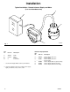
List of Models Model No. 288665 288666 G3000 Flow Meter and Informer Display Remote Informer Display with 1/2 in. pipe mounting hardware G3000 Flow Meter with 50 ft. sensor cable (P/N 243554) Order kit 243554 288667 Remote Informer Display with 3/4 in. pipe mounting hardware G3000 Flow Meter with 50 ft. sensor cable (P/N 243554) Order kit 243554 288668 Remote Informer Display with 1 in. pipe mounting hardware G3000 Flow Meter with 50 ft.
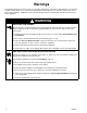
Warnings The following warnings are for the setup, use, grounding, maintenance, and repair of this equipment. The exclamation point symbol alerts you to a general warning and the hazard symbol refers to procedure–specific risk. Refer back to these warnings. Additional, product–specific warnings may be found throughout the body of this manual where applicable.
EQUIPMENT MISUSE HAZARD INSTRUCTIONS Equipment misuse can cause the equipment to rupture, malfunction, or start unexpectedly and result in serious injury. D This equipment is for professional use only. D Read all instruction manuals, tags, and labels before operating the equipment. D Use the equipment only for its intended purpose. If you are uncertain about usage, call your Graco distributor. D Do not alter or modify this equipment. Use only genuine Graco parts and accessories.
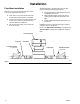
Installation Typical Installation: Remote Informer Display and Meter (in a non-hazardous area) A D B C TI0443A Fig. 1 Ref. No. Part No. Description A B C D 948924 239716 * n Cable Meter Informer Control Box * Informer Display Models See Informer Display Models Chart for part numbers. Ref. No. Part No. Description C 288666 Remote display with 1/2 in. . . . . . . . . . . . . . . . . . . pipe mounting C 288667 Remote display with 3/4 in. . . . . . . . . . . . . . . . . . .
Installation The Informer display is an easy to use means of collecting fluid data to help reduce fluid waste and improve processes.
Installation Flow Meter Installation Refer to Fig. 2 to locate and install the flow meter, connectors, and fluid shutoff valves. D D D Flow volume can only be measured at the location where the flow meter is installed. Install a check valve to prevent back-flow. The arrows on the flow meter and check valve show the direction of fluid flow. The shutoff valves allow you to isolate the meter for service.
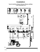
Installation Informer 013 (288666, 288667, 288669, 288670) Typical Installation: Remote Informer Display and Meter in Non-hazardous Area Fig.
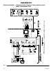
Installation Remote Informer Display in Non-hazardous Area, Meter In Hazardous Area former 638 (288666, 288667, 288669, 288670) 9636B Typical Installation: Fig.
Installation Display Jumpers and Terminals JP2 The default jumper positions are shown in Table 1. The hardware configuration of the Informer display can be customized by changing jumper positions and wiring the terminals for the desired configuration. Jumper JP2 determines the source of power for the Informer display. When pins 1 and 2 are jumpered together, the Informer display is configured to receive power from an external DC power source, which must be connected to terminals 1 and 2 on connector J1.
Installation Terminals J2 – 1 and 2 Batch Reset Connector J1 terminals are numbered 1 through 4. Connector J2 terminals are numbered 1 through 8. Terminal definitions and typical wiring connections are shown in figures 3 to 4 on pages 9 to 10. An external signal applied to this input will reset the Batch Totalizer to zero if the totalizer is a type t1 or t3, or it will preset the Batch Totalizer if it is a type t2 (see setup parameters for details, page 17). Terminal 1 is the positive connection.
Installation 3. Always ground the fluid supply unit, using one of the following options: Grounding a. Mount the meter to a grounded conductive surface, or WARNING FIRE, EXPLOSION, AND ELECTRIC SHOCK HAZARD Proper electrical grounding of your system is essential. For your safety, read the warning section, FIRE, EXPLOSION, OR ELECTRIC SHOCK HAZARD, on page 4. b. Connect the conductive fluid hose to the meter inlet and outlet, or c. Connect a ground wire to the meter’s M6 mounting holes. 4.
Operation Operating the Informer Display Press any button to activate the Informer display (bring it out of “Sleep Mode”). The Informer has two operation modes: Run Mode (page 15) and Setup Mode (page 16). Icons As you move through the various Informer screens, you will notice icons appear at the bottom of the screen. The icons for Flow Rate, Batch Totalizer, and Maintenance Totalizer also appear on the Informer buttons. The icons represent various run and setup functions and alarm activation.
Operation Run Mode When the Informer display is in Run Mode, the current flow rate, batch totalizer, maintenance totalizer, and grand totalizer values can be viewed for the flow meter the Informer display is connected to. cc/min Flow Rate Monitoring Screen Alarms There are two ways the Informer display can be used to notify a user when the Batch Totalizer Target, Main- tenance Totalizer Target, or the Flow Rate Maximum or Minimum Thresholds have been reached.
Operation Setup Mode The Setup Mode is used to set parameters for monitoring fluid flow with the Informer display. Setup parameters are described on page 17. To enter Setup Mode, hold down the enter button same button sequence will exit Setup Mode. , then press the up arrow button Setup Mode is represented by a letter and number on the left side of the display, which indicate the current setup parameter. Setup Mode starts with the A1 (Batch Totalizer Units). .
Operation Setup Parameters NOTE: If the related alarm output is enabled, the values set for the Batch Totalizer Target, Maintenance Totalizer Target, and Flow Rate Maximum and Minimum Thresholds determine when an external alarm will be signaled. See Alarm Outputs on page 18. A1 – Batch Totalizer Units Select liters (L), cubic centimeters (cc), gallons (gal), or ounces (oz) for units of measure. The default setting or down arrow buttons to is cc.
Operation D1 – Flow Rate Units Alarm Outputs Setting the maximum and minimum flow rate threshold values will provide an alarm to alert you that the process is out of specification. The next series of setup parameters allow you to enable (1) or disable (0) the alarm outputs. If the alarm outputs are enabled, the Informer display will send a signal to turn on an external alarm to signal an alarm condition. The default setting for all the alarms is disabled (0).
Operation F3 – Flow Rate Alarm Enable J1 – Battery Powered Operation If enabled (F3=1), the user alarm output will activate when the flow rate is greater than the flow rate maximum threshold value. The user alarm output is also active if the flow rate is less than the flow rate minimum threshold value for three consecutive samples. The alarm occurs after three consecutive samples to avoid alarms when stopping or starting fluid flow.
Operation Examples NOTE: In the following examples it is assumed: D External power supply is used D Meter-mounted Informer package (243312) is used D Default K-factor of 0.12 cc/pulse is accurate D Jumper JP2 is set to position 1–2, all other jumpers and setup parameters not specifically mentioned in the example, are assumed to be in the default position or setting Example 1: Gun Flow Rate Detection Example 2: Batch Dispense Control The informer is used to monitor the flow rate through a gun.
Operation Example 1: Gun Flow Rate Detection (continued) INFORMER SETUP RECIPE Date: ___________ Informer S/N: ____________ Setup Parameters Description A1 Batch Totalizer Units A2 Batch Totalizer Target Value A3 Batch Totalizer Type Setup Configuration l, cc, gal, oz t1 t2 t3 l cc gal oz t1–Count Up, Auto Reset t2–Count Down, Auto Reset t3–Count Up, Manual Reset B1 Maintenance Totalizer Units B2 Maintenance Totalizer Target Value C1 Grand Totalizer Units l cc gal oz D1 Flow Rate
Operation Example 2: Batch Dispense Control (continued) INFORMER SETUP RECIPE Date: ___________ Informer S/N: ____________ Setup Parameters Description A1 Batch Totalizer Units A2 Batch Totalizer Target Value A3 Batch Totalizer Type Setup Configuration l cc gal oz 185.
Operation INFORMER SETUP RECIPE Date: ___________ Informer S/N: ____________ Setup Parameters Description Setup A1 Batch Totalizer Units l A2 Batch Totalizer Target Value A3 Batch Totalizer Type t1 cc t2 gal oz t3 t1–Count Up, Auto Reset t2–Count Down, Auto Reset t3–Count Up, Manual Reset B1 Maintenance Totalizer Units l cc gal oz B2 Maintenance Totalizer Target Value C1 Grand Totalizer Units l cc gal oz D1 Flow Rate Units l cc gal oz D2 Flow Rate Maximum Threshold Valu
Troubleshooting WARNING NOTE: The sensor is not a serviceable part. Replace it if it is malfunctioning. SKIN INJECTION HAZARD To reduce the risk of an injection injury or other serious injury, follow the Pressure Relief Procedure on page 13 before checking or servicing the meter assembly.
Troubleshooting Problem Cause Solution No signal for alarm situation Incorrect setup Correct configuration Incorrect wiring Correct wiring Blown F3 fuse (User Alarm) Replace fuse; see page 35 for replacement fuses Blown F4 fuse (Batch Alarm) Replace fuse; see page 35 for replacement fuses External power is off Turn on power Auto reset enabled for batch totalizer Change to manual reset Cannot retain setup parameters Flash memory cycle life exceeded Replace programmed circuit chip Display r
Maintenance Battery Replacement (See Fig. 10) WARNING FIRE AND EXPLOSION HAZARD To reduce the risk of fire or explosion: D Do not remove or install the battery in a hazardous location. D The internal (9a and 9b or 16) and external (44 or 64) ground wires for the display must be correctly connected. NOTE: D See page 35 for battery part numbers. D Numbers in parenthesis in the text refer to the reference numbers in the figures (Fig.) and in the parts lists.
Maintenance 14 15 11 REF A 9 B C 31 REF 3 9b 9a 43 8 REF Display Assembly to Mount on Meter 3 7 8 10 11 A 51 REF 1 11 35 or 54 31 or 51 12 3 44 or 64 8 REF Remote Display Assembly 9631A Fig. 10 Remotely Mounted Display Assembly (continued) 9. Plug the removable terminal blocks into their receptacles (14, 15). 10. Check the condition of the gasket (10) and replace it if it is damaged. 11.
Parts Model 288680 Informer Display, for installation on meter (meter not included) 2 1 4 6 14 3 15 7 5 8 10 9 11 12 9630B Ref. No. 1 2 3 Part No. Description 193647 243552 4 5 243551 243549 6 280529 6a 115839 HOUSING, upper display KIT, membrane switch BATTERY, 9 volt (See chart on page 35) KIT, LCD display KIT, programmed integrated circuit chip KIT, circuit board, display; includes item 6a S JUMPER; not shown 28 Qty. 1 1 1 1 1 1 3 Ref. No. 7 8 Part No.
Parts Model 288679 Informer Display, for remote installation 2 1 4 6 14 3 15 7 5 10 8 11 12 16 9630A Ref. No. 1 2 3 Part No. Description 193647 243552 4 5 243551 243549 HOUSING, upper display KIT, membrane switch BATTERY, 9 volt (See chart on page 35) KIT, LCD display KIT, programmed integrated circuit chip KIT, circuit board, display; includes item 6a S JUMPER; not shown COVER, circuit board 6 280529 6a 7 115839 193650 312013 Qty. 1 1 1 1 1 1 Ref. No. 8 Part No.
Parts Model 288665 Informer Display, with Graco G3000 flow meter 42 41 40 34 37 35 38 43 36 32 31 33a 33b 33c 33d 33e 33 33f 33g 33h Ref. No. 31 32 33 Part No. Description 243309 113517 239719 33a 110580 33b 33c 33d 33e 33f 33g 33h 34 * 110588 239718 192383 192387 * 290579 288680 35 195874 SENSOR O-RING, fluoroelastomer BODY, gear meter, includes items 33a–33h S SCREW, cap, socket hd.
Parts 62 60 55 53 54 56, 57 54 51 52 58 61 9639A Model 288666 Informer Display, remote installation, 1/2 in. pipe mount Ref. No. 51 52 53 54 Part No. Description 196301 195857 113517 195874 55 288679 56 57 115698 195889 ADAPTER PLATE, adapter mounting O-RING, fluoroelastomer SCREW, mach., phillips pan hd., M4 x 8 DISPLAY, remote; See page 29 for parts PLUG, dome BUSHING, strain relief Qty. 1 1 1 4 Ref. No. 58 Part No.
Parts Model 288668 Informer Display, remote installation, 1 in. pipe mount See drawing on page 31 Ref. No. 51 52 53 54 Part No. Description 196301 195857 113517 195874 55 288679 56 57 115698 195889 ADAPTER PLATE, adapter mounting O-RING, fluoroelastomer SCREW, mach., phillips pan hd., M4 x 8 DISPLAY, remote; See page 29 for parts PLUG, dome BUSHING, strain relief Qty. 1 1 1 4 Ref. No. 58 Part No.
Parts Model 288717 Informer Display, with Graco G3000HR flow meter 42 41 40 34 37 35 38 43 36 32 31 33a 33b 33c 33d 33e 33 33f 33g 33h Ref. No. 31 32 33 Part No. Description 243309 113517 244291 33a 110580 33b 33c 33d 33e 33f 33g 33h 34 * 110588 244290 197142 192387 * 291643 288680 35 195874 SENSOR O-RING, fluoroelastomer BODY, gear meter, includes items 33a–33h S SCREW, cap, socket hd.
Parts Model 288670 Informer Display, remote installation, din rail mount 62 55 59 53 60 56, 57 61 54 51 52 58 Ref. No. 51 52 53 54 Part No. Description 196301 195857 113517 195874 55 288679 56 57 58 115698 195889 195875 ADAPTER PLATE, adapter mounting O-RING, fluoroelastomer SCREW, mach., phillips pan hd., M4 x 8 DISPLAY, remote; See page 29 for parts PLUG, dome BUSHING, strain relief SCREW, mach., phillips pan hd., M4 x 16 Qty. 1 1 1 2 1 2 2 4 TI0078 Ref. No. 59 Part No.
Parts Model 234106 Remote G3000HR Flow Meter Installation Kit 71 72 TI0077 Ref. No. 71 Part No. Description Qty. 244292 72 948924 G3000HR FLOW METER; See manual 308778 for parts CABLE ASSY., 50 ft. (15.24 m) 1 1 9 Volt Battery for Display Brand Ultralife* Duracell Duracell EverReady EverReady * Part No. U9VL MN1604 PC1604 EN22 522 Type Lithium Alkaline Alkaline Alkaline Alkaline An Ultralife battery is shipped with the Informer display in order to replace the Alkaline test battery.
Dimensions Model 288665 and 288717 Informer Display, with Graco flow meter 4.02 in. (102.1 mm) M6 4.90 in. (124.5 mm) 5.63 in. (143.0 mm) 1.73 in. (43.9 mm) 2.16 in. (54.86 mm) 1/4–18 npt(f) inlet/outlet 3.35 in. (85.1) mm 9633A Model 288666, 288667, 288668 Informer Display, pipe mount 4.02 in. (102.1 mm) 4.90 in. (124.5 mm) See Table See Table 9639A Model Pipe Diameter Height 288666 0.50 in. (12.7 mm) 5.42 in. (137.7 mm) 288667 0.75 in. (19.1 mm) 5.52 in. (140.2 mm) 288668 1.00 in.
Dimensions Model 288669 Informer Display, wall mount 4.02 in. (102.1 mm) 6.00 in. (152.4 mm) 4.90 in. (124.5 mm) 4.90 in. (124.5 mm) 5.25 in. (133.4 mm) 0.28 in. (7.1 mm) 2.30 in.(58.4 mm) 1.50 in.(38.1 mm) 1.06 in.(26.9 mm) 9638A Model 288670 Informer Display, din rail mount 4.02 in. (102.1 mm) 4.90 in. (124.5 mm) 4.21 in. (106.
Technical Data Display RS–485 Communication Port 6 digit, 1 inch (25.4 mm) high LCD display D Keypad D 4 button membrane with tactile feedback on 3 buttons Power Requirements D D D 9 VDC internal battery at 2 mA (display on) Or 12 to 24 VDC external power supply at 10 mA Replaceable fuse, reverse polarity protected Pulse Input D D D 8 VDC at 2.5 mA to 24 VDC at 16 mA Current sinking or sourcing 1000 pulses/sec.
Technical Data Display Parameters Display updated in approximately 1/2 sec intervals. D Grand Totalizer D Selectable Units (L, gal, cc, oz) D Count Up D Backed up to non-volatile memory D Maximum displayed value: “999999” D Maximum stored value: 429,496,729.5 cc (accessible with Modbus) D Batch Totalizer D Selectable Units (L, gal, cc, oz) D Count Up or Down D Settable Target D Maximum displayed value: “99999.9” D Maximum stored value: 429,496,729.
Graco Standard Warranty Graco warrants all equipment manufactured by Graco and bearing its name to be free from defects in material and workmanship on the date of sale to the original purchaser for use. With the exception of any special, extended, or limited warranty published by Graco, Graco will, for a period of twelve months from the date of sale, repair or replace any part of the equipment determined by Graco to be defective.