
Technical data

312013 7
Installation
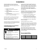
The Informer display is an easy to use means of
collecting fluid data to help reduce fluid waste and
improve processes. The Informer display performs the
following functions:
D Monitors flow rate real time
D Outputs a signal when flow rate preset is
reached
D Tracks batch totals
D Outputs a signal when a batch total preset is
reached
D Tracks grand totals
D Communicates with data reporting software for
process or environmental reporting
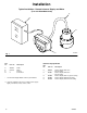
The Informer display can be directly mounted to the
Graco flow meter or remotely mounted from a flow
meter. Informer display models are available for
mounting on a din rail, wall, or pipe.
The Informer display can be battery powered when it is
mounted on the flow meter or externally powered when
it is remotely mounted from the meter.
Installing Equipment in Hazardous
and Non-hazardous Areas
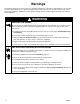
WARNING
FIRE, EXPLOSION, AND ELECTRIC
SHOCK HAZARD
To reduce the risk of fire, explosion, or
electric shock:
D All electrical equipment must only be installed
by a qualified electrician.
D Understand and follow your local code and
safety regulations for hazardous location wiring
of intrinsically safe circuits.
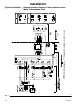
The Graco Informer display and fluid flow meter, are
intrinsically safe for Class I; Division 1; Group D haz-
ardous indoor (NEMA 12) locations when installed as
shown in Fig. 4, page 10; “Typical Installation: Remote
Informer Display in Non–hazardous Area, Meter in
Hazardous Area”. Refer to ANSI standards ISA-
RP12.6, NEC Article 504 and the Canadian Electrical
Code Appendix F.
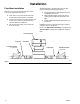
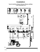
The wiring schematics on pages 9–10 show typical
installations of a flow meter and display. Your installa-
tion may consist of different components. Not all the
components shown are supplied by Graco.
D To install a flow meter and display in a non-
hazardous area, refer to Fig. 3, page 9.
D To install an intrinsically safe flow meter in a
hazardous area and the Informer display in a
non-hazardous area, refer to Fig. 4, page 10.
Do not use more than 50 ft. (15 m) of cable between
the meter and display.
Follow grounding instructions on page 13.
When intrinsically safe barriers are used for hazardous
installations, close attention should be paid to selecting
an appropriate power supply so that valid signals are
applied to the inputs and outputs in accordance with
the technical data on page 38.
Cable shields should be connected to the chassis
ground, not the power supply common, inside the
Informer Display housing. The battery cover screw,
mounting adaptor (51) or sensor housing (31) may be
used for this ground.
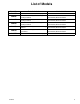
Recommended Cables
For power, communication, and I/O
Brand Alpha Part No. Type
Alpha 58612 2 pairs, 22 AWG
Alpha 58613 3 pairs, 22 AWG
Alpha 58616 6 pairs, 22 AWG