
User's Manual


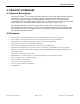

PRODUCT OVERVIEW
001-9193-001 Version 2 Page 9 of 52 Sentry 4G
TM
User Manual
Disabled
Acquired
Activity
Satellites
in View
Satellites
3G (WWAN)
I/F
Disabled
Connected
RX/TX
Activity
Failed to
establish
connection
Establishing
Connection
Fault
N/A
4G (WWAN)
I/F
Disabled
Connected
RX/TX
Activity
Failed to
establish
connection
Establishing
Connection
Fault
N/A
WiFi (client)
N/A
Connected
RX/TX
Activity
Failed to
establish
connection
Establishing
Connection
Fault
N/A
WiFi (Access
Point)
IF/Disabled
Ready
RX/TX
Activity
N/A
N/A
Fault
N/A
ETH0
No link
100mbps
link
RX/TX
Activity
10 mbps
link
N/A
N/A
N/A
ETH1
No activity
N/A
RX/TX
Activity
N/A
N/A
N/A
N/A
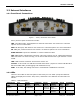
2.4 RJ-45 Ethernet Port Integration Parameters
Table 2 below provides the information to purchase Ethernet cables to integrate the Sentry
4G product into your system.
Note:
The Sentry 4G unit can accept either a standard or cross over Ethernet cable. A standard
Ethernet cable is one that has matching pin assignments on both ends (T568A or T568B),
while a cross over Ethernet cable is one that has a T568A termination on one end and
T568B on the other.
Table 2 - Standard RJ-45 Ethernet Pin-outs
Pin
Function
T568A
T568B
1
TX +
White/Green
White/Orange
2
TX -
Solid Green
Solid Orange
3
RX +
White/Orange
White/Green
4
Solid Blue
Solid Blue
5
White/Blue
White/Blue
6
RX -
Solid Orange
Solid Green
7
White/Brown
White/Brown
8
Solid Brown
Solid Brown
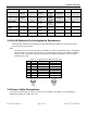
2.5 Power Cable Connections
If using the provided power cable to connect to a DC supply (car battery) use the following
diagrams and table to connect the unit.