
User's Manual

PRODUCT OVERVIEW
001-9193-001 Version 1 Page 7 of 48 Sentry 4G 900
TM
User Manual
2.3 External Interfaces
2.3.1 Front Panel Connections
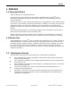
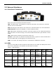
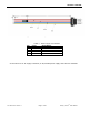
Figure 1 - Dataradio Sentry 4G Router Front Panel
Sentry 4G router front panel connections include:
TRX: Two TNC female, Transmit/Receive antenna connections. See section 2.6 “Antenna
options” for more information.
WiFi: RP-SMA jack, WiFi antenna. See section 2.6 “Antenna options” for more information.
ETH0 and ETH1: Inputs for standard or crossover Ethernet cable
GPS: SMA female, GPS antenna connector. This input requires a 3.3V, GPS antenna with an
SMA connection. For best coverage, use an active GPS antenna with a gain between 10 and
30 dB.
USB: USB A Female connector. Reserved for future use.
Console: 3-wire serial in a USB Mini B female form factor (requires a custom USB Mini B to
EIA-232-F DB9 cable) for debugging and maintenance only.
PWR: 10-30 VDC; the mating connector is a Weidmuller 1615800000 connector.
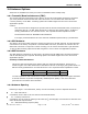
2.3.2 LEDs
There are seven LEDs on the front panel of the Sentry 4G unit. Each can display three colors:
Red, Green, and Amber. The definition for each LED is as follows:
Table 1 - LED Definitions
INDICATOR
OFF
SOLID
GREEN
FLASHING
GREEN
SOLID
AMBER
FLASHING
AMBER
SOLID
RED
FLASHING
RED
PWR
(Power)
No Power
Power on
App.Running
Test Mode
Hardware
Power up
Sequence
Software
boot
sequence
Power
Supply
Fault
N/A
STAT (Status)
No Power
Status
Normal
N/A
Warning
Factory
Defaults
Fault
N/A
GPS
GPS
Disabled
Position Fix
Acquired
1PPS
Activity
No
Satellites
in View
Acquiring
Satellites
Fault
N/A
4G (WWAN)
I/F
Disabled
Connected
RX/TX
Activity
Failed to
establish
connection
Establishing
Connection
Fault
N/A
WiFi (client)
N/A
Connected
RX/TX
Activity
Failed to
establish
connection
Establishing
Connection
Fault
N/A
WiFi (Access
IF/Disabled
Ready
RX/TX
N/A
N/A
Fault
N/A