
Install Guide

12
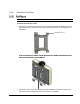
1.3 Interfaces
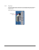
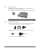
The unit is installed vertically, where the integrated GPS antenna is located on the
top panel
(
facing the sky). All other connections, including the optional GPS external antenna connections
are located on the
bottom
panel.
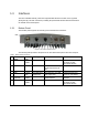
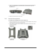
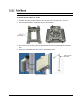
1.3.1 Bottom Panel
The interface panel supports the antenna, power and Ethernet connections.
Figure 3. Pico Base Interface Panel
The following table provides a description of the Pico Base bottom panel connectors and ports.
Table 1. Bottom Panel Connectors
No.
Connector
Name
Connector
Type
Cable Type
Description
Connected to
1
ANT1
N type
Female
RG 214/U
RF antenna connection
external antenna or
Screwed-on omni-
directional antenna
2
Console
RJ45
Cat5 ETH
Low level CLI for CalAmp
technical personnel. RS-
232
Computer
3
DC + ETH
RJ45
Cat5 ETH
DC 1.5A + Ethernet Cat5
PoE data adapter
4
GND
1 screw
ETSI
#10 AWG bare
copper wire
Grounding lug. #10 AWG
bare copper wire
Central earth ground,
Tower or pole chassis
5
GPS
(optional)
TNC
Female
RG-59
Base Station
Synchronization
Optional External GPS
antenna
6
ANT2
N type
Female
RG 214/U
RF antenna connection
external antenna or
Screwed-on omni-
directional antenna
GND