
User's Manual


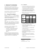

Table Of Contents
- PRODUCT OVERVIEW
- Installation
- Operating Description
- Trouble-Shooting and Testing
- Radio Programming and Adjustments
- Series II Radio Programming
- Series II Radio Tuning
- S
- Specifications
120 20170-302 Paragon
PD
Technical Manual
5
1.5 Packaging
Each Paragon
PD
product normally leaves the
factory packaged as follows:
• A Series II Dataradio base station “Radio
assembly”
• A dual power supply assembly
• A Dataradio BDLC
PD
model
• A Radio Interface Cable to link the Radio
assembly to the BDLC
PD
:
18-inch long “Y” cable; DB-25 female to
dual DB-25 female (p/n 730 03374-102) for
connection between backplane PCBs and
BDLC
PD
.
• One standard seven-foot 120VAC power
cord
• Two DC power cables to connect the radio
assembly to the dual power supply assem-
bly.
• Courtesy small parts kit
Frequently, Paragon
PD
product components are
field-assembled prior to customer delivery.
The cabinetry may then be supplied in one of
several custom rack-mount configurations that
may also include fan, backhaul modems,
duplexer/filters/combiners, and ancillary
equipment.
If damage has occurred to the equipment during
shipment, file a claim with the carrier immedi-
ately.
2. Installation
2.1 Overview
The cabinet and rack-mount housing the
Paragon
PD
’s radio assembly and the BDLC
PD
is
generally installed in a sheltered facility.
Occasionally located adjacent to the nerve
center of the user’s network, it is often located
near tower sites or at remote locations where it
operates unattended.
Furnishings needed include power, cabling, and
installation of antenna, landline or microwave
modem, and host PC or portable computer. De-
tails of these are outside the scope of this man-
ual. This manual covers the radio assembly and
the BDLC
PD
that includes the modem.
2.2 Location
Be sure to place the Paragon
PD
in such a way
that:
• The LEDs can be seen (as an aid in trouble-
shooting)
• Access to the antenna connector and to the
back connectors is possible without remov-
ing the unit
• Sufficient air may flow around the unit to
provide adequate cooling.
2.3 Electrical
Standard 120 VAC electrical power is required.
It should be capable of providing at least 10A to
power Paragon
PD
(<6A) and ancillary equip-
ment.