
User Manual

120 20191-002 Paragon-III Technical Manual
5
2. Installation
2.1 Overview
The cabinet and rack-mount housing the Paragon-III’s radio assembly and the BDLC-III is generally
installed in a sheltered facility. Occasionally located adjacent to the nerve center of the user’s
network, it is often located near tower sites or at remote locations where it operates unattended.
Furnishings needed include power, cabling, and installation of antenna, landline or microwave mo-
dem, and host PC or portable computer. Details of these are outside the scope of this manual. This
manual covers the radio assembly and the BDLC-III that includes the modem.
2.2 Location
Be sure to place the Paragon-III in such a way that:
• The LEDs can be seen (as an aid in troubleshooting)
• Access to the antenna connector and to the back connectors is possible without removing the unit
• Sufficient air may flow around the unit to provide adequate cooling.
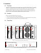
2.3 Front View:
Figure 1 - Typical rack-mount multi-modules "Radio Assembly"
Figure 2 - Typical rack-mount dual "Power Supply"
OL Stby On
Power
OL Stby On
Power
T800
II
Slimline
®
Dual Power Supply Module
®
Receiver
®
Gating
Gate
Line
Level
Supply
®
Exciter
Carrier
On
Line
Sensitivity
Supply
Microphone
®
Sensitivity
Monitor
Volume
Off
On
Monitor
Mute
Receiver
Gating
Gate
Line
Level
Supply
Sensitivity
Monitor
Volume
Off
On
Monitor
Mute
Excellence in Radio
Communications
® ®
Speaker Panel
programming
port
RX2RX1
OFF
SPEAKER
SELECT SWITCH
A
ir Flow
BDLC-III