
User Manual
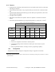
Table Of Contents
120 20195-100 Preliminary Paragon4 – UHF, 700, & 800MHz User Manual
i
i
1. PRODUCT OVERVIEW...................................................................................................................................1
1.1 INTENDED AUDIENCE....................................................................................................................................1
1.2 GENERAL DESCRIPTION ................................................................................................................................1
1.2.1 Features...................................................................................................................................................2
1.2.2 Configuration...........................................................................................................................................2
1.3 FACTORY TECHNICAL SUPPORT ....................................................................................................................3
1.4 PRODUCT WARRANTY ..................................................................................................................................4
1.5 REPLACEMENT PARTS...................................................................................................................................4
1.5.1 Factory Repair.........................................................................................................................................4
1.6 PACKAGING ..................................................................................................................................................4
2. INSTALLATION................................................................................................................................................5
2.1 OVERVIEW ....................................................................................................................................................5
2.2 LOCATION.....................................................................................................................................................5
2.3 REAR VIEWS .................................................................................................................................................6
2.4 ELECTRICAL..................................................................................................................................................7
2.4.1 Standard Power Supply Configuration....................................................................................................7
2.4.1.1 DC Power Supply Connection & Torque Settings .......................................................................................... 7
2.4.1.2 Power Indications............................................................................................................................................ 8
2.4.2 Backplane Fuses......................................................................................................................................8
2.5 ANTENNA......................................................................................................................................................9
2.5.1 Overview..................................................................................................................................................9
2.5.2 Cabling and Connection..........................................................................................................................9
2.6 COMPLETING THE PHYSICAL INSTALLATION .................................................................................................9
2.7 CHECKING OUT NORMAL OPERATION...........................................................................................................9
3. OPERATING DESCRIPTION........................................................................................................................10
3.1 RADIO ASSEMBLY.......................................................................................................................................10
3.1.1 Receiver module.....................................................................................................................................10
3.1.2 Exciter module.......................................................................................................................................11
3.1.3 BSC module ...........................................................................................................................................11
3.1.4 Speaker panel.........................................................................................................................................12
3.1.5 Power Supply Modules (T809)...............................................................................................................13
3.1.5.1 Power Supply Rear Connections................................................................................................................... 14
4. OPERATION & CONFIGURATION ............................................................................................................15
4.1 BROWSER-BASED INTERFACE .....................................................................................................................15
4.1.1 Interface Setup and Status .....................................................................................................................15
4.2 LAN SETUP ................................................................................................................................................16
4.3 DEFAULT IP SETTINGS................................................................................................................................16
4.3.1 Ethernet Interface 1 (DATA)..................................................................................................................16
4.3.2 Ethernet Interface 2 (SETUP)................................................................................................................16
4.3.3 RF Interface...........................................................................................................................................16
4.4 IP NETWORK SETTINGS ..............................................................................................................................17
4.4.1 IP Network Settings (with Host) ............................................................................................................17
4.4.2 IP Network Settings (with Router).........................................................................................................17
4.5 LOGIN SCREEN............................................................................................................................................18
4.5.1 Initial Installation Login........................................................................................................................18
4.6 WEB INTERFACE .........................................................................................................................................19
4.6.1 Apply, Cancel, Save Config, and Reset Unit Buttons & Help Icon........................................................19
5. TROUBLE-SHOOTING AND TESTING......................................................................................................20
5.1 EQUIPMENT REQUIRED ...............................................................................................................................20
5.2 RECOMMENDED CHECKS ............................................................................................................................20
5.3 ADDITIONAL TEST DETAILS.........................................................................................................................24
5.3.1 Carrier Deviations.................................................................................................................................24
5.3.2 PF Switch...............................................................................................................................................24
5.3.2.1 Stopping the Airlink and Alternate Test Tone Selection Method.................................................................. 24