
Installation Guide


156-90000-508 G3
Installation Guide
9
3. Operating Description
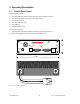
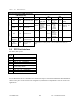
3.1 Front & Rear Panels
The front panel includes:
• One mini-UHF type female antenna connector for the auxiliary receiver
• One SMA type female connector for the GPS receiver
• Three LED indicators
• Two DE-9F RS232 ports
• One USB port
• Onr RJ45 Ethernet port
The rear panel includes:
• One mini-UHF type female antenna connector for the main transceiver
• One 3-pin pigtailed DC Power connector with ignition sense
Figure 5 - Front and rear panels
®
USB
RX
GPS
G3
PWR RX TXPGM
DEV-1DEV-2
6.000"
2.0
00"
ETH
LNK
ACT