
Installation Guide


156-90000-508 G3
Installation Guide
12
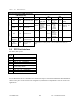
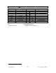
Table 2 - Tests
CHECKLIST A
STEP ACTION
EXPECTED RESULTS at
25°C
MEASURE WITH IF NOT?
G3
units are set and characterized at the factory to optimize performances. It is not recommended to try to readjust the units.
1
Power-up LED Sequence
as per Table 1 - G3 LEDs indications
2
Connect and save config
Press Dataradio test com-
mands Get button
as per Dataradio test commands Help content
3
Main transceiver Output
Power
Command TXON (Unmod)
30W
Service monitor
set to read power
or
50W in-line watt-
meter
Refer to factory technical
support.
4
Main transceiver Reflected
Power
Command TXON (Unmod)
< 5% of forward power or as
specified by System Eng.
10W in-line watt-
meter
Check for bad connections,
damaged coax cable, etc.
5
Carrier Frequency Error
Command TXON (Unmod
± 300 Hz
Service monitor
set to read fre-
quency error
Refer to factory technical
support.
4
TX Deviation (in kHz)
Command TX7 (Modulated)
Carrier will be modulated with a
1 kHz tone.
8.0kHz
Tolerance is +5%, -10% for all bit rates.
Service monitor set
to read deviation
(IF filter set to Mid
or 30 kHz position)
Refer to factory technical
support.
6
Set the service monitor to generate at the unit antenna jack the RF levels mentioned below. The carrier generated
should be modulated with a 1.0 kHz tone at deviation as per step 4 above.
7
Main Rec. RSSI checks
-70dBm
-110dBm
-120dBm
- 70 dBm +/-3
-110 dBm +/-3
-120 dBm +/- 3
Dataradio test
commands
8
Aux Receiver
repeat as per step 7
same as step 7
Dataradio test
commands
The RSSI checks give a gen-
eral indication of receivers'
health
Refer to factory technical
support only if RX data per-
formance degradation is no-
ticed combined to out of tol-
erance RSSI readings.
1 (unless you have set a lower value). Note that readings less than 30 may be due to losses in cables used for testing. Check also
your wattmeter frequency calibration curve. Do not be too ready to condemn the transmitter.