TTU TTU-4530™ Hardware and Installation Guide IMPORTANT: DO NOT INSTALL OR USE THE SOFTWARE OR DOCUMENTATION UNTIL YOU HAVE READ AND AGREED TO THE LICENSE AGREEMENT AND REVIEWED THELIMITED WARRANTY AND REGULATORY INFORMATION INFORMATION.
Welcome to the 4530™ Hardware and Installation Guide. This manual is intended to give you information on the basic setup and installation of the CalAmp 4530™ product(s) including hardware descriptions, environmental specifications, wireless network overviews and device installation. 1.1 About This Manual The 4530™ is one of the most flexible economy mobile tracking hardware products available.
1.4 About the CalAmp Location Messaging Unit-4520™ The CalAmp Location and Messaging Unit-4530™ (4530™) is a mobile device that resides in private, commercial or government vehicles. The 4530™ is a single box enclosure incorporating a processor, a GPS receiver, a wireless data modem, and a vehicle-rated power supply. The 4530™ also supports inputs and outputs to monitor and react to the vehicular environment and/or driver actions.
A wireless data network An 4530™ Host Device (GPS NMEA only) An LM Direct™ communications server Backend mapping and reporting software which typically includes mapping and fleet reporting functions PULS™ LMU Manager™ Basic System Architecture
2.2 Component Descriptions 2.2.1 Wireless Data Network The Wireless Data Network provides the information bridge between the LM Direct™ server and the 4530™. Wireless data networks can take a variety of forms, such as cellular networks, satellite systems or local area networks. Contact the CalAmp sales team for the networks available to the 4530™. 2.2.2 4530™ The 4530™ is responsible for delivering the location and status information when and where it is needed.
Present historic information received from the 4530™, typically in a report/chart style format Request location updates from one or more 4530s™ Update and change the configuration of one or more 4530s™ 2.2.5 PULS™ PULS™ (Programming, Update and Logistics System) is CalAmp’s web-based maintenance server offering out-of-the-box hands free configuration and automatic post-installation upgrades.
To ensure proper operation in such an environment, the 4530™ was subjected to standard tests defined by the Society of Automotive Engineers (SAE). The specific tests included temperature, shock, vibration, and EMI/EMC. These tests were performed by independent labs and documented in a detailed test report. In accordance with Appendix A of SAE J1113 Part 1, the Unit is considered a “Functional Status Class B, Performance Region II” system that requires Threat Level 3 Testing.
The LMU-4520™ 4520™ supports vehicles with 12 or 24 VDC systems including transients and electrical system noise; this includes ranges from 7 to 32 VDC. Electrostatic Discharge (ESD) No damage or performance ance degradation after the ESD disturbance. SAE Test: SAE J1113 Part 13 Power Consumption Deep Sleep: 2mA Sleep on Network (SMS): 10mA Sleep on Network (GPRS): 20mA 3.3.1 Accessories See the Harness Diagrams page for more information on LMU accessories, and supported products table. 3.3.
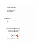
To serially connect to Aux1, simply connect the following wires together from the power harness to the screw terminal block - red to red, black to black, yellow to green/brown and orange to blue/brown.
Input-5 Input-6 Input-7 Input-8 Input-9 Input-10 Input-11 Input-12 Input-13 Input-14 Input-15 Output-0 Output-1 Output-2 Output-3 Output-4 Output-5 Output-6 Output-7 Output-8 Output-9 Output-10 Output-11 Output-12 Output-13 ADC-0 ADC-1 ADC-2 ADC-3 ADC-4 ADC-5 ADC-6 ADC-7 ADC-8 ADC-9 Host/Aux-1 Aux-2 Aux-3 In-5 sel In-6 sel In-7 sel Motion VBUS Active Pwr State Vbatt Low 1BB Detect Batt Virt Ign Pure Virt Ign Radio Active Wakeup Out-1 Out-2 Pwr Switch Chrg Disable ADC1 0=Standard 1=4-20mA mode ADC2 0=Sta
Sleep Processor LMU STM32F205 App ID 321-HSPAg6 3.4.1 3-Axis Accelerometer Input The LMU-4530™ supports an internal 3 Axis Precision Accelerometer as one of its discreet inputs. When the LMU is moved in any direction, the associated input will be in the High state. If the LMU’s accelerometer does not detect motion, then the input will be in the Low state. No external connections are required for this functionality to be operational. 3.4.
Condition LED 2 GPS Off Off GPS On Slow Blinking GPS Time Sync Fast Blinking GPS Fix Solid 4 Configuration and Activation This section details how to quickly get an LMU-4530™ provisioned and configured to point at a specific server. It is assumed that a PEG script has already been created and is being managed through LMU Manager or PULS™, the CalAmp Maintenance System.
AT$APP PARAM 2319,0,ddd.ddd.ddd.ddd AT$APP PARAM 768,0,ddd.ddd.ddd.ddd (32-bit products only) AT$APP PARAM 769,0,ppppp Where ddd.ddd.ddd.ddd is the publicly addressable IPV4 address of your LM Direct™ server and ppppp is the UDP port number. 4. Alternatively if a URL has been set up for your LM Direct™ server, the LMU may be programmed with: AT$APP PARAM 2319,0,myURL.MyCompany.Com Where myURL.MyCompany.com is the URL assigned to the server. 5.
!RP?769,0 .2 Auto provisioning of GSM or HSPA LMUs For certain operators, the LMU can auto-populate the APN, username and password settings based on the Mobile Country Code (MCC) and the Mobile Network Code (MNC) of the SIM. Upon inserting a new SIM the APN, username and password will switch to the new SIM card's defaults if the MCC and MNC values change.
o Password: pass T-Mobile (MCC 310, MNC 16, 20, 21, 22, 23, 24, 25, 26, 27, 31, 58, 66, 80) o APN 0: INTERNET2.VOICESTREAM.COM o APN 1: INTERNET3.VOICESTREAM.COM T-Mobile UK (MCC 234, MNC 30,31,32) o APN 0 & 1: general.t-mobile.uk o Username: user o Password: wap TelCel Mexico (MCC 334 MNC 02) o APN 0 & 1: INTERNET.ITELCEL.COM o Username: webgprs o Password: webgprs2002 Telstra Australia (MCC 505, MNC 01, 11, 71, 72) o APN 0 & 1: telstra.internet Vodafone Ireland (MCC 272, MNC 01) o APN 0 & 1: isp.vodafone.
AT$APP PARAM 1024,35,1,0 Auto-provisioning occurs when the LMU detects a SIM with a new operator ID (i.e. the first 6 digits of the IMSI) or when Bit 0 of S155 is cleared and the GPRS context is blank (i.e. Parameter 2306,0). 4.3 Activating GSM or HSPA LMU using AT Commands Check with the CalAmp Sales team for availability of the LMU-4530™ with GSM or HSPA modems. For a GSM/GPRS operator you will get the LMU in one of two varieties, one with a SIM and one without.
The activation sequence for a GSM LMU would therefore look as follows: AT$APP PARAM 2306,0,“myAPN.myOperator.com” AT$APP PARAM 2306,1,“myAPN.myOperator.com” AT$APP PARAM 2314,0,“myUSername” AT$APP PARAM 2315,0,“myPassword” For a blank APN the following command can be used: AT$APP PARAM 2306,0,“” (for a blank APN) Only enter this next command if you have been given a non-zero PIN as any errors may lock you out of the modem.
GPRS APN: IP:Public Quality of Srvc: 1,0,0,3,0,0 GSM Class: B The SIM carrier is located inside the LMU-4530™ housing on the back center of the device.
4.5 Activating a CDMA LMU-4530™ Check with the CalAmp Sales team for availability of the LMU-4530™ with CDMA modems. For CDMA devices, the activation sequence you will use varies from carrier to carrier. Each of the supported carriers is documented below. To obtain an account, a CDMA carrier will generally ask for three things, the Manufacturer, the Product Type and the ESN. Obviously the first two items are answered by “CalAmp LMU”. The last one is a little misleading.
Channel: 0 Band:Side: 800:B Base Station ID: 0 Network ID: 0 System ID: 4 ESN (Modem S/N: 2676319948 [9F8566CC] Phone Number: 1234567890 IMSI: 310001234567890 CarrierConfig: 5 Note that the Phone Number should match the MDN value the carrier gave you. The last 10 digits of the IMSI field should match the MIN/MSID value they gave you.
Once configured, you may verify that the LMU-4530’s™ modem has registered to the CDMA network. Enter: AT$APP COMM STATUS? The response should be similar to: CDMA Service: IS-2000 Connection: Yes RSSI: -80 dBm Channel: 0 Band:Side: 800:B Base Station ID: 0 Network ID: 0 System ID: 4145 ESN (Modem S/N: 2676319948 [9F8566CC] Phone Number: 1234567890 IMSI: 310001234567890 CarrierConfig: 1 The Phone Number field should match the value you used in step 3 or 4.
Input and output cables Relays LMU peripherals (i.e. Serial adapter, jPOD, TetheredLocator) Host serial devices (e.g. PDAs, laptops, other serial devices) 5.2 Plan The Installation Verify Power, Ground and Ignition. Be sure to check each source (power, ground and ignition) to ensure that the proper signaling exists. This is typically accomplished with a multi-meter.
Typical installations will place the LMU under the vehicle dash board, or in the trunk. Make sure you can get access to the unit afterwards as under some circumstances it may be necessary to add additional wiring or connections to the LMU. 5.2.2 Placement of Antennas There are effectively three options for placements of an antenna: Roof-mount (magnetic or thru-hole) Glass-mount Covert (e.g. under the seat, dash, etc…) Comm Antenna Placement Guidelines The Comm.
GPS Antenna Placement Guidelines In order to maximize the performance of the LMU the GPS antenna should have a clear view of the sky. When installing the GPS antenna on a vehicle, make sure that there are no obstructions close to the antenna that might block the view 360° to the horizon. Things like air horns, lights, vents, etc… should not block the antenna beyond 5° above the horizon.
When dealing with combination antennas, it is more important to considered GPS performance over Comm performance. GPS signal strengths are much lower than those typically seen by cellular networks supported by the LMU. In order to maximize the performance the LMU should have a clear view of the sky as possible. When installing the GPS antenna in a vehicle, make sure that there are as few obstructions as possible close to the LMU that might block the view 360° to the horizon.
It is best not to place the LMU unit in an unusually warm location such as directly near heater vents, near hot engine components or in direct sunlight. The maximum temperature that can be tolerated by the LMU is described in the LMU Environmental Specifications section. 5.2.5 Visibility of Diagnostic LEDs Status LED lights on the front of the LMU unit can provide valuable information about the operation of the LMU.
Typically, the LMU should be placed under the passenger seat or dashboard of the vehicle. LMUs with internal antennas should be placed to maximize their GPS performance. A typical location include under the dash close to the front wind-shield. Attach the LMU to the solid body of the vehicle, not to plastic panels. The LMU can be placed out of sight by removing interior trim and molding to expose available space, then replacing the trim once the LMU is in place 5.3.2 Connect power, ignition, and ground.
GPS Antenna Location 5.3.4 Mount the Comm. Antenna. When using separate Comm and GPS antennas, it is best to locate the Comm. Antenna at least 3 feet from the GPS antenna. Ensure that the cable is not crushed during installation or normal vehicle operation. Again, the Comm. Antenna must be located at least 20cm away from vehicle passengers, other personnel, or bystanders in order to comply with FCC radio frequency exposure limits. Window Mount Antenna Location 5.3.
Connect any peripherals to the LMU Plug in the power harness. The physical installation of the LMU hardware is now complete. Completed Install – separate antennas Completed Install - Internal antennas 5.4 Installation Verification In many cases it is desirable to verify that an installed 4530™ is working properly. That is, installers should verify that the GPS and communications functions of the 4530™ are working properly before departing the installation site.
5.4.1 Comm Verification Installers should first verify that the 4530™ has been acquired and has registered to the wireless network. This may be verified in one of two ways. First, installers may look at the Comm LED (i.e., the one closest to the SMC antenna connector). If this LED is solid, then the LMU has registered to the network and established a data session.
If any of the responses return Not-Acquired or Not-Registered (and the APN is correct), the wireless network operator should be contacted for further troubleshooting. Please note that it may take several seconds (or longer) for the 4520™ to communicate with the modem and acquire the wireless network. 5.4.2 GPS Verification The next step is to verify that the GPS receiver is seeing enough satellites to obtain a valid GPS position. Again, installers have two choices on how to perform this verification.
INBOUND 0 URL myURL.myCompany.com INBOUND 1 ADDR 0.0.0.0:20500 INBOUND 1 URL INBOUND 2 ADDR 0.0.0.0:20500 INBOUND 3 ADDR 0.0.0.0:20500 The installer will need to verify with a backend technician that the, URL (myURL.myCompany.com ), IP address (ddd.ddd.ddd.ddd) and port () are correct. The second step is to verify that the 4530™ is sending data. The best way to do this is to force the 4530™ to send in an unacknowledged Event Report (i.e.
APP: o : The Application ID value of the LMU indicating the host platform and the wireless networking technology of the LMU. o : The current firmware version in use by the LMU COM: o : This is the signal strength the wireless modem sees from the network. In general the LMU is at least scanning for the network if the RSSI is not -113. o [./d/D]: If the character ‘D’ is present, it indicates the LMU had a data session established when it responded to the status request.
The current Access Point Name in use by a GSM LMU. GPS: o [Antenna ]: This field, if present, indicates a problem with the LMU’s GPS antenna. A value of Short indicates that the antenna cable has likely been crushed. A value of Open indicates that the antenna cable is either cut or disconnected. A value of Off indicates that the LMU’ GPS receiver is off. o [No Time Sync]: If this field is present, it indicates that the LMU’s GPS receiver has not been able to find even a single GPS satellite.
o : This is the current IP address in use by the LMU. This value should match the IP address of your LM Direct™ server. o : This is the current UDP port the LMU will use to deliver its LM Direct™ data. This value should match UDP port you are using on your LM Direct™ server. It is typically 20500. o : This is the current UDP/IP messaging protocol in use by the LMU. In general it should be LMD. Example GSM Response APP:081 8.
Port, App Watcher Service and/or other software products licensed by CalAmp for use in computer applications development or integration including the computer programs, libraries and related materials either contained on the media provided to you by or from CalAmp, or which you have received or downloaded electronically. “Application” means a compiled or executable software program created by Developer that uses some or all of the functionality of the Software.
Duration: This License Agreement is effective from the day you install or start using the Software, or receive or download it electronically, and continues until terminated. If you fail to comply with any provision of the License, termination is automatic, without notice from CalAmp and without the necessity for recourse to any judicial authority. Upon termination, you must destroy the Related Materials, the Software, Documentation and all Software and Documentation copies.
Developer(s) License—Uses Not Permitted: Unless Otherwise Agreed To In Writing with CalAmp, You May Not (1) Make derivative works including but not limited to translations, adaptations, arrangements or any other alteration (each of which would become the property of CalAmp or its licensors, as applicable) or make copies of the Software or Documentation except as permitted above; (2) Make copies of the Related Materials; (3) Use any CalAmp product to translate the product of another licensor unless you have
Rent, lease, sublicense or lend the Application or its rights under the license; (4) Alter, decompile, disassemble or reverse engineer the Application; (5) Make any attempt to unlock or bypass any initialization system or encryption technique utilized by the Application; or (6) Alter, remove or obscure any proprietary legend, copyright or trademark notice contained in or on the Application.
purchase and date, must be sent in a traceable manner to: CalAmp DataCom Inc., 1401 North Rice Ave. Oxnard, CA 93030. Disclaimer Regarding the Software, Documentations and Related Materials: THE SOFTWARE, DOCUMENTATION AND RELATED MATERIALS ARE PROVIDED “AS IS.
of the Software, Documentation and Related Materials and supersedes all proposals, oral or written, and any other communications you may have had prior to purchasing your license; (3) Except for the price and delivery terms agreed upon by both parties, the terms and conditions of this License Agreement shall supersede those set forth in any purchase order where the purchase order conflicts or is inconsistent with or adds to the terms and conditions of this License and those superseded purchase order terms a
The 4530™ complies with RF specifications when used at a distance of 10 mm from your body. Ensurethat the device accessories, such as a device case and deviceholster, are not composed of metal components. Keep thedevice away from your body to meet the distancerequirement. Gardez le 10mm de l'appareil à partir de votre corps pour répondre à l'exigence de la distance. FCC Rules and Industry Canada (IC) regulatory information Compliance Statement (Part 15.
Le présent appareil est conforme aux CNR d'Industrie Canada applicables aux appareils radio exempts de licence. L'exploitation est autorisée aux deux conditions suivantes : (1) l'appareil ne doit pas produire de brouillage, et (2) l'utilisateur de l'appareil doit accepter tout brouillage radioélectrique subi, même si le brouillage est susceptible d'en compromettre le fonctionnement.