
User's Manual


To serially connect to Aux1, simply connect the following wires together from the power harness to
the screw terminal block
blue/brown. Make sure to do a continuity check to
black wires and thus this step is necessary to ensure that you are using the correct ground outlet)
Serial Adapter part number:
LMU™ Serial Adapter
Note for Serial Adapter: The ON/OFF switch of
'OFF' position.
3.4 I/O Descriptions
The LMU-453
0™ provides the following inputs and outputs (I/O):
LMU-4530Z/TTU-4x30
App Id:
320-HSPA EHS5
321-HSPA EHS6
322-GSM BGS2
323-LTE LE910
324-CDMACE910
325-LTE LHS5
Processor:
STM32F205-768
GPS:
UBLOX G7020
Input-0 Ignition
Input-1 In-1 sel
Input-2 In-2 sel
Input-3 In-3 sel
Input-4 In-4 sel
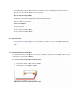
To serially connect to Aux1, simply connect the following wires together from the power harness to
the screw terminal block
-
red to red, black to black, yellow to green/brown and orange to
blue/brown. Make sure to do a continuity check to
determine pin configurations(There are multiple
black wires and thus this step is necessary to ensure that you are using the correct ground outlet)
Serial Adapter part number:
134364-SER
Note for Serial Adapter: The ON/OFF switch of
the 134364-
SER cable should be set to the default
0™ provides the following inputs and outputs (I/O):
To serially connect to Aux1, simply connect the following wires together from the power harness to
red to red, black to black, yellow to green/brown and orange to
determine pin configurations(There are multiple
black wires and thus this step is necessary to ensure that you are using the correct ground outlet)
SER cable should be set to the default