
User's Manual
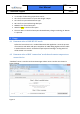
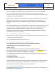
Table Of Contents
- 1 Introduction
- 2 Description
- 3 Setup
- 3.1 LMU BT LE driver streams and serial port configuration parameters setup example.
- 3.2 LMU BTST SPP driver streams and serial port configuration parameters setup example.
- 3.3 LMU Bluetooth driver configuration parameters setup.
- 3.4 LMU user serial message configuration parameters setup example.
- 3.5 BTCS version format.
- 3.6 BTCS default Pass key.
- 3.7 Verification of LMU BTST SPP mode “Data” state example.
- 3.8 Verification of LMU configuration for BLE “connection” mode example.
- 3.9 Verification of LMU BLE “Advert broadcast scanning” mode configuration example.
- 4 Usage
- 4.1 Demonstration of LMU BT SPP mode.
- 4.2 Demonstration of BLE “connection” mode based remote temperature sensor device.
- 4.2.1 Send command “Enable notifications on Temperature sensor attribute profile”.
- 4.2.2 Send command “Start temperature conversion”.
- 4.2.3 Observe the GPSTRAX server User 0 temperature data.
- 4.2.4 Disable BLE sensor “notifications”.
- 4.2.5 Send command “Stop” temperature conversion.
- 4.2.6 “GPSTRAX” server report contains temperature sensor data.
- 4.3 Demonstration of BLE “broadcast scanning” mode based remote KeyFob DriverID device.
- 5 PWA Label
- 6 Integration Instructions

User Manual
Version:
1.0
Feature: Bluetooth Support
Page #:
10 of 20
There is a limitation of the length of the command which has to be less than 32 BYTES.
4.2.1 Send command “Enable notifications on Temperature sensor attribute profile”.
Populate the “Data” field in Figure 2 with the hexadecimal representation of ATGW,1,38,2,1
- 0x415447572C312C33382C322C31.
Where ATGW is the BTCS API for characteristic “WRITE” (GATT WRITE). It is used to write
the characteristic value or descriptor from a server when the attribute handle of the
characteristic value is known. 1 is the BTCS connection handler, and can be an arbitrary
number.
Use ATCS command to get the correct connection handler index as explained in 3.6. The rest
of the command is “SensorTag” temperature sensor specific. 38 is the SensorTag board
temperature sensor “Notification settings” handler index. 2 is the “Notifications”
configuration parameter byte length. The last field is the parameter value - 1 stands for
“Turn ON” operation , 0 for “Turn OFF”.
4.2.2 Send command “Start temperature conversion”.
Populate the “Data” field in Figure 2 with the hexadecimal representation of ATGW,1,41,1,1
- 0x415447572C312C34312C312C31
The command fields description is the same as 4.1.
4.2.3 Observe the GPSTRAX server User 0 temperature data.
474154545F56414C2C312C303033372C312C342C44394646313030430D
In LMU debug log the same message can be observed:
SERMSG: RcvMsg:
474154545F56414C2C312C303033372C312C342C44394646313030430D
Converted to ASCII format the same message is: GATT_VAL,1,37,1,4,D9FF100C0D, where
1 corresponds to the connection ID ranging from 1 to 65535,
37 corresponds to the GATT characteristic handler index specific to TI temperature sensor,
1 is GATT notification,
4 is data length in Bytes,
D9FF100C0D represents the sensor data.
The data colored in yellow represent the temperature, where 0xD9 is the lowest significant
byte of the Object temperature, 0xFF- MSB of object temperature, 0x10 – LSB of the
ambient temperature, 0x0C – MSB of the ambient temperature.
4.2.4 Disable BLE sensor “notifications”.
Populate the data field in Figure 2 with the hexadecimal representation of ATGW,1,38,2,0 -
0x415447572C312C33382C322C30