Paradise Series Owner’s Manual Moorea • Hawaiian • Martinique • Kauai ® ® ®
WELCOME Watkins Manufacturing Corporation congratulates you on your decision to enjoy the finest spa available... Welcome to the growing family of Caldera® Spa owners. Owner’s Manual This Owner’s Manual will acquaint you with the operation and general maintenance of your new spa. We suggest that you take some time to carefully review all sections. Please keep this manual available for reference.
TABLE OF CONTENTS SAFETY INFORMATION MAINTENANCE • Important Safety Instructions...................................................................... 2 • Filter Maintenance. ................................................................................... 24 • Important Spa Instructions.......................................................................... 4 • Filter Cartridge Removal and Cleaning Instructions................................ 24 INSTALLATION • Site Preparation. .............
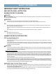
SAFETY INFORMATION IMPORTANT SAFETY INSTRUCTIONS Read and follow all instructions Avoiding The risk to children Danger: RISK OF CHILD DROWNING. Extreme caution must be exercised to prevent unauthorized access by children. To avoid accidents, ensure that children cannot use a spa unless they are supervised at all times. Warning: • To reduce the risk of injury, do not permit children to use this spa unless they are closely supervised at all times.
SAFETY INFORMATION • DO: • • • Install your spa in such a way that drainage is away from the electrical compartment and from all electrical components. Be sure your spa is connected to the power supply correctly - use a licensed electrical contractor. Disconnect the spa from the power supply before draining the spa or servicing the electrical components. Test the Ground Fault Circuit Interrupter(s) before each use. Don’t: • • • • Use the spa with the equipment compartment door removed.
SAFETY INFORMATION • • Pregnant or possibly pregnant women should limit spa water temperatures to 100°F (38°C). Failure to do so may result in permanent injury to your baby. Do not use spa immediately following strenuous exercise. Avoiding the risk of skin burns: • • To reduce the risk of injury, before entering a spa, the user should measure the water temperature since the tolerance of temperature-regulating devices varies.
INSTALLATION Deck Installation WARNING WARNING To be certain your deck can support your spa, you must know the deck’s maximum load capacity. Consult a qualified building contractor or structural engineer. To find the weight of your spa, its contents and occupants, refer to the Spa Specification chart on back cover. This weight per square foot must not exceed the structure’s rated capacity, or serious structural damage could result.
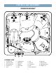
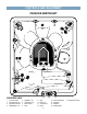
Controls and Equipment paradise moorea® 14 14 14 3 1 1 6 3 6 5 8 10 5 12 9 6 19 5 5 4 3 3 9 10 16 10 5 3 7 5 5 4 2 18 3 15 11 17 14 1 1 OVERHEAD VIEW 1. 2. 3. 4. 5. Air Control Valve Temperature Sensor Euro Directional Jet Euro-Pulse® Jet Air Jet 13 6. 7. 8. 9. 10. 1 VersaSsage® Jet Euphoria® Jet Assist Bar Diverter Valve Drain 11. 12. 13. 14. 15. 6 Light Ozone Jet Control Panel Pillow Filter Compartment 16. 17. 18. 19.
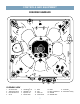
Controls and Equipment Paradise HAWAIIAN 13 13 6 1 3 4 3 4 4 4 4 5 9 8 4 1 11 9 14 9 15 8 3 4 3 4 7 10 1 5 5 3 2 18 16 13 13 17 Overhead View 1. 2. 3. 4. Air Control Valve Temperature Sensor Euro Directional Jet Air Jet 5. 6. 7. 8. VersaSsage® Jet AdaptaFlo™ Jet Euphoria® Jet Diverter Valve 9. 10. 11. 12. 1 12 Drain Light Ozone Jet Control Panel 13. 14. 15. 16. 7 1 Pillow Filter Compartment Waterfall Waterfall Valve 17. Assist Bar 18.
Controls and Equipment Paradise Martinique® 12 12 1 1 2 5 2 6 8 7 10 8 4 8 13 6 9 2 6 12 2 2 16 17 Overhead View 1. 2. 3. 4. Air Control Valve Euro Directional Jet Temperature Sensor AdaptaSsage™ Jet 15 3 14 1 5. 6. 7. 8. AdaptaFlo™ Jet VersaSsage® Jet Diverter Valve Drain 9. 10. 11. 12. Light Ozone Jet Control Panel Pillow 8 1 11 13. 14. 15. 16. Filter Compartment Assist Bar Waterfall Waterfall Valve 17.
Controls and Equipment Paradise Kauai® 10 2 2 4 3 3 1 8 12 5 6 7 2 4 2 13 14 2 11 1 OVERHEAD VIEW 1. 2. 3. Air Control Euro Directional Jet Euro-Pulse® Jet 4. 5. 6. VersaSsage® Jet Diverter Valve Drain 7. 8. 9. 9 Light Ozone Jet Control Panel 9 1 10. Pillow 11. Filter Compartment 12. Assist Bar 13. Temperature Sensor 14.
ELECTRICAL INSTALLATION ELECTRICAL REQUIREMENTS AND PRECAUTIONS Your Caldera® Spa has been carefully designed to give you maximum safety against electrical shock. Connecting the spa to an improperly wired circuit will negate many of the spa’s safety features. Improper wiring may also cause electrocution, risk of fire, and other risks of injuries.
ELECTRICAL INSTALLATION Paradise series wiring diagram 230 Volt Permanently Connected WARNING! THE EXACT PHYSICAL LOCATION OF THE TERMINALS ON THE GFCI BREAKER WILL VARY BETWEEN MANUFACTURERS. CONNECTING THE HOT WIRE TO THE NEUTRAL TERMINAL WILL CAUSE IRREVERSIBLE DAMAGE TO THE CONTROL BOX. ** GRD System Ground Terminal ** Refer to NEC 250-122 (table) NOTE: The wire connections to GFCI breakers are for reference only.
START-UP AND REFILL PROCEDURES Your Caldera® spa has been thoroughly tested during the manufacturing process to ensure reliability and long-term customer satisfaction. A small amount of water may have remained in the plumbing after testing and, as a result, may have spotted the spa shell or the spa siding prior to delivery. Before filling the spa, clear all debris from the spa and wipe the spa shell clean with a soft rag.
START-UP AND REFILL PROCEDURES 9. The spa temperature is pre-programmed to reach 102°F (39°C), and will normally do so within 18 to 24 hours. You may raise the water temperature by pressing the “TEMP (▲)” button on the control panel once to display the temperature, then pressing it again within five seconds to raise the temperature, or lower it by pressing “TEMP (▼)” button once to display the temperature, then pressing it again within five seconds to lower the temperature.
CUSTOMIZING YOUR MASSAGE Euro Directional and Euro-Pulse® Jets - The Euro Directional jets, with eyeball nozzles, deliver a direct, more focused massage. The Euro-Pulse jets feature a special insert that creates a soft, pulsating, rotary massage. The Euro-Pulse jet cap assemblies may be removed if you want a more powerful, direct massage in the wrist locations. To do this, rotate the jet face counter clockwise and pull off. Then simply press and twist Euro Directional Jet into place.
JET MENU moorea® Jet Pump 1–Jet System 1 Jet Pump 1–Jet System 2 Located in UltraMassage™ lounge – left • 3 VersaSsage® jets • 2 Euro Directional jets Located in Reclining Seat • 2 VersaSsage® jets – on back wall • 6 Sole Soothers® Located in UltraMassage lounge – left • 3 VersaSsage jets • 2 Euro Directional jets Located in Reclining Seat • 2 VersaSsage jets – on back wall • 1 Euphoria® jet in footwell Jet Pump 2–Jet System 2 Jet Pump 2–Jet System 1 • Waterfall Located in Single Jet Seat • 1
JET MENU hawaiian Jet Pump 1–Jet System 2 Jet Pump 1–Jet System 1 • 2 VersaSsage® jets in front left corner • 1 AdaptaFlo™ jet on back center wall Located in LumbarSsage® seat – back right • 4 Euro Directional jets • 2 VersaSsage® jets Ecsta Seat® Located in – back left • 10 Euro Directional jets Jet Pump 2–Jet System 1 Jet Pump 2–Jet System 2 • Waterfall • 6 Sole Soothers® in footwell Located in UltraMassage seat – front right • 3 VersaSsage jets • 2 Euro Directional jets • 1 Euphoria® jet in foot
JET MENU martinique® Jet Pump 1–Jet System 1 Located in Ecsta Seat® – back left : • 8 Euro Directional jets Located in LumbarSsage® Seat – back right • 4 Euro Directional jets • 2 VersaSsage® jets Located in Center seat • 1 AdaptaFlo™ jet Jet Pump 2–Jet System 2 Jet Pump 2–Jet System 1 • 2 AdaptaSsage™ jets on left wall • 2 VersaSsage jets in foot well Located in UltraMassage lounge – front: • 2 Euro Directional jets • 3 VersaSsage jets • Waterfall Located in UltraMassage lounge – front • 6 Sole Soothe
JET MENU kauai® Jet Pump – Jet System 1 Jet Pump – Jet System 2 Located in UltraMassage lounge • 6 Sole Soothers® • 3 VersaSsage® jet • 2 Euro Directional jets Located in Ecsta Seat® • 8 Euro Directional jets • 2 Euro-Pulse® jets Combination Jet System Located in UltraMassage lounge • 6 Sole Soothers • 3 VersaSsage jets • 2 Euro Directional jets Located in LumbarSsage® seat • 4 Euro Directional jets • 2 VersaSsage jets Jet Pump diverter in mid position activates both Jet Pump Systems 1 and 2.
OPERATING INSTRUCTIONS CONTROL PANELS TEMP (up) button Increases the temperature Moorea® • Hawaiian JETS 1 button Operates jet pump 1 AIR button Operates the air jets SET button Increases the temperatures used to initiate advance panel features CLEAN button Operates a ten-minute clean-up cycle LIGHT button Operates the interior & exterior lighting TEMP (down) button Decreases the temperature JETS 2 button Operates jet pump 2 & spas with Waterfall TEMP (up) button Increases the temperature Martiniqu
OPERATING INSTRUCTIONS LOCKING FEATURES The locking features, TEMPERATURE LOCK and SPA LOCK, are enabled from the control panel by a specific combination of buttons. Once enabled, a lock will remain active until the specific button combination is applied to disable the lock. Even if power is disconnected from the spa and soon thereafter reapplied (such as a power outage), the lock will remain in place.
OPERATING INSTRUCTIONS LIGHT CONTROL The “LIGHT” button activates the light and controls the intensity. Pressing the “LIGHT” button operates the light as follows: • 1st press of the “LIGHT” button – light will turn on to the maximum intensity. • 2nd press of the “LIGHT” button – light will turn to medium intensity. • 3rd press of the “LIGHT” button – light will turn to low intensity. • 4th press of the “LIGHT” button – light will turn off.
EQUIPMENT COMPARTMENT JET PUMP SIDE 7 6 5 3 3 4 4b - Discharge 2 1 8 4a - Suction Hawaiian*, Moorea®*, and Martinique® 1. 2. 3. 7 6 3 4 4 1 4. 5. 6. 7. 8.
EQUIPMENT COMPARTMENT CONTROLS SIDE 4 1 3 6 5 2 Advent® Control Box System EnergyPro® Circulation Pump EnergyPro Flow-Through Heater Monarch® CD Ozone Generator (optional) SpaGlo® LED Light System (optional) Pressure Switch 23
MAINTENANCE FILTER MAINTENANCE At least once a week, check and clean the skimmer basket and weir to ensure proper filter flow. Remove leaves, foreign matter, and debris. It is very important to keep your spa filter cartridge clean and free of particles to ensure proper water flow. A clean filter permits the hydrotherapy system to function properly and also allows more efficient filter cycles. Depending on how frequently your spa is used, we recommend cleaning the spa filter cartridge every four weeks.
MAINTENANCE DRAINING YOUR SPA 1. Turn off all GFCI breakers in sub-panel, or main electrical panel. 2. Locate the main drain valve for the spa. Pull on handle (Step1) until you reach the mid position (Step 2) then rotate handle slightly to fully extended drain tube (drain cap and 1” of the drain tube is exposed) then remove the drain cap (Step 3) . NOTE: You will not be able to remove drain cap in mid position.
MAINTENANCE 7. Using a long-extension funnel, pour anti-freeze into all standpipes, filter suction fittings, jet orifices and water feature orifices. Also, add anti-freeze to the SPA FROG® canister. Add enough anti-freeze to ensure adequate protection – in many cases, you will see the liquid in the orifice, or coming out of another location. CAUTION: Use only Propylene Glycol as your anti-freeze. This is non-toxic. Never use an automobile anti-freeze (Ethylene Glycol) since it is toxic! 8.
WATER QUALITY AND MAINTENANCE CARE OF THE SPA COVER WARNING: The cover is a manual safety cover that meets or exceeds all prevailing requirements of ASTM Standards for spa safety covers when installed and used correctly as of the date of manufacture. Non-secured or improperly secured covers are a hazard. Open the cover to its fully open position before use. VINYL COVER The vinyl spa cover is an attractive, durable foam insulation product.
WATER QUALITY AND MAINTENANCE It’s important to have clean water. Water maintenance is one of the least understood, yet most important areas of spa ownership. Your dealer can guide you through the process of achieving and maintaining perfect water in your spa, given your local conditions. Your program will depend on your water’s mineral content, how often you use your spa, and how many people use it. WATER TERMINOLOGY The following chemical terms are used in this Water Quality and Maintenance section.
WATER QUALITY AND MAINTENANCE Methods for Testing the Spa Water Accurate water testing and analysis is an important part of effectively managing your spa water. You must have the ability to test for: • Total Alkalinity (TA) • Calcium Hardness (CH) • pH • Sanitizer Two types of testing methods are recognized and recommended by Watkins Manufacturing Corporation: 1. The Reagent Test Kit is a method which provides a high level of accuracy. The reagents come in either liquid or tablet form. 2.
WATER QUALITY AND MAINTENANCE D. If the Total Alkalinity is too high, the pH level will tend to be high and may be difficult to bring down. It can be lowered by using sodium bisulfate(pH/Alkalinity Down). E. Once the TA is balanced, it normally remains stable, although the addition of more water with a high or low alkalinity will raise or lower the TA reading of the water. F. When the Total Alkalinity is within the recommended range, proceed to the next step. Balancing the Calcium Hardness (CH) A.
WATER QUALITY AND MAINTENANCE THE WATKINS WATER MAINTENANCE QUICK REFERENCE GUIDE Ideal Range (ppm) Steps 1 Total Alkalinity 2 Calcium Hardness 3 pH 4 Sanitizer What Chemicals to Use Min. Max. To Raise To Lower 80 180 Sodium Hydrogen Carbonate or Sodium Bicarbonate Sodium Bisulfate 150 400 Calcium Hardness Increaser Use a mixture of 75% hard water and 25% soft water or use a Stain and Scale Inhibitor 7.2 7.
WATER QUALITY AND MAINTENANCE FOLLOWING THE SPA FROG® SANITIZER ROUTINE During the first month of ownership, measure the sanitizer residual daily in order to establish the correct setting on cartridges for User Load and Usage Time versus Sanitizer Needed. • The User Load of the spa is the number of times anyone enters the spa. • The Usage Time is simply the amount of time a user spends in the spa. • Sanitizer Needed is the amount needed to accommodate the number of users and their combined usage time.
WATER QUALITY AND MAINTENANCE watkins water treatment guide At spa startup or refill Prior to each use (Test before adding any chemicals; do not add any chemicals if proper or higher levels are found.) Follow spa Start-Up and Refill Procedures. Add one (1) tablespoon of Monarch® MPS Plus (monopersulfate)* per 250 gallons. Once a week Add three (3) tablespoon Monarch MPS Plus (monopersulfate)* per 250 gallons. Every four months Drain spa, replace mineral cartridge, and refill your spa.
WATER QUALITY AND MAINTENANCE 5. Place the end of the tubing into the vinegar, making certain that the end of the tubing sits at the bottom of the container. 6. Reconnect power to the spa. 7. Run the spa until all 16 ounces of the vinegar are gone. This should allow an ample flow of vinegar to be run through the injector and clear the blockage. 8. Disconnect power to the spa. 9. Remove the empty cup or bucket. 10. Reinstall the tubing to the bottom of the ozonator. 11.
WATER QUALITY AND MAINTENANCE Common Water Chemistry Questions Question: Why is the use of a floater not recommended to sanitize my spa water? Answer: Watkins Manufacturing Corporation does not recommend the use of a floater for three reasons: 1. The floater is unable to control the rate at which the sanitizer is dissolved into the water. When a floater is first placed in a spa, the sanitizer level can be extremely high.
SERVICE MISCELLANEOUS SERVICE INFORMATION The control and high limit thermostats are equipped with electronic sensors that are connected to the spa’s plumbing. Never cut, or kink the wires that connect the sensors to the thermostats within the control box. The jet pump is equipped with a thermal overload cutoff switch that is designed to protect the pump from overheating. If the pump shuts itself off in an older spa, it could indicate failure of the pump motor bearings.
SPA TROUBLESHOOTING If your spa doesn’t seem to be working the way you believe it should, please review the “start-up” and “operation” instructions in this manual. If this doesn’t help you correct the problem, follow the appropriate instructions below. If the problem is still not resolved, call your Caldera® dealer. general operation troubleshooting guide Problem Probable causes Solutions Entire spa is inoperative.
Utopia and Paradise Series Spas Watkins Manufacturing Corporation (“Watkins”) warrants to the original consumer purchaser (“you”) the following about your new Utopia or Paradise Series spa, when purchased from an authorized dealer/service provider (“dealer”). 10 YEAR NO LEAK SHELL WARRANTY WARRANTY PERFORMANCE Watkins warrants against water loss due to defects in the Utopia and Paradise series spa shell for ten years.
NOTES 39
NOTES 40
Ele Re ctrica qu ire l me nts dw eig ht De a we igh t* Fil led Dr yw eig ht Eff filt ectiv er are e a He a (W ter att s) Wa ca ter pa cit y Fo o dim tprin t en sio ns He igh t PARADISE Series Spa specifications Moorea® (MOA) 7'0" x 7'7" 36" 75 square feet 4,300 420 gallons 870 lbs. 5,490 lbs. 115 230 volt, 30 or 50 amp lbs. per Single phase GFCI square protected circuit foot Hawaiian (HAA) 7'0" x 7'0" 36" 75 square feet 4,300 380 gallons 800 lbs. 5,180 lbs.