
User Guide


Function
The balancing valve accurately controls the flow rate of heating and
cooling transfer fluid supplied to air handlers, fan coils and terminal units;
or where flow balancing is required in solar thermal systems. Proper
hydronic system balancing ensures the system operates according to
design specifications, providing satisfactory thermal comfort with low energy
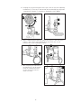
consumption.The flow meter is housed in a by-pass circuit on the valve body
and can be shut off during normal operation. The flow meter permits fast and
easy circuit balancing without added differential pressure gauges and charts.
QuickSetter™ Balancing Valve with flow meter, ANSI Flanged
132 Series
©
Copyright 2020 Caleffi
H0003350.0
4
www.caleffi.com
Technical specifications
Materials
Valve
Body: cast iron
Ball: brass
Ball control stem: brass, chrome plated
Ball seal seat: R-PTFE
Control stem guide: PTFE
Seal: peroxide-cured EPDM
Flow meter
Body and headwork: brass
Bypass shutoff control stem: brass, chrome plated
Springs: stainless steel
Seal: EPDM
Flow meter float and indicator cover: PSU
Performance
Suitable Fluids: water, glycol solutions
Max. percentage of glycol: 50%
Max. working pressure: 150 psi (10 bar)
Working temperature range: 14 – 230°F (-10 – 110°C)
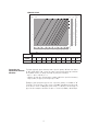
Flow rate range unit of measurement: gpm
Flow rate scales: size 2½”- 30 – 105 gpm
size 3” - 38 – 148 gpm
size 4” - 55 – 210 gpm
Accuracy: ±10%
Control stem angle of rotation: 90°
Adjustment handwheel diameter: 5½"
Flanged connections: 2½", 3", 4" ANSI B16.1 125 CLASS RF
Flow rate correction factor: 20% – 30% glycol solutions: 0.9
40% – 50% glycol solutions: 0.8
These items are designed for use in closed hydronic systems. Do not use in plumbing applications. These
items do not meet the low-lead plumbing standards of U.S. and Canada.
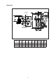
Product range
132 Series Balancing valve with flow meter sizes 2½”, 3”, and 4” with ANSI flange connections.
1