
User Guide


Operating Principle
The 142 series balancing valve is a
hydraulic device that controls the flow
rate of a fluid. Turning the knob moves a
plug within the fluid stream which varies
the flow rate. The flow rate is determined
according to the pressure drop value
measured by a differentialpressure meter
connected to the pressure test ports.
The opening position is indicated by the
numbered indicator (fig. E):
- The turn indicator (1) shows a
regulating scale scale from 0 to 4
(0 closure, 4 complete opening).
Turning the knob manually through
360° causes the indicator to move by
one unit.
E
Use of the balancing
valve: setting the
flow rate (fig F-G)
NOTE: the indications + and – on the
drawings refer to the pressure upstream
and downstream of the component
whose pressure differential is to be
measured.
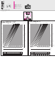
For the connection of the pressure test ports
of the valve (2) with a differential pressure
measuring device (3), use a pair of fittings
with a measuring probe (fig. F).
F
2
4
3
1
a) As the thermal fluid passes,
measure the Δp of the valve with
any suitable differential pressure
measuring device(fig. G);
b) Using the “Hydraulic
characteristics” sheet (sheet
code 18203 supplied in the
pack), find the flow rate value
that is passing through the valve,
consulting the diagram “Δp-flow
rates” corresponding to the size
of the valve used.
c) Turn the knob and repeat steps a)
and b) until you reach the desired
value.
Correction for liquids of different densities
If using liquids with a density different from water at 70°F (20°C)
≈ 62.4 lb/ft
3
( ≈ 1 kg/dm3), correct the value of the measured head loss Δp
using the following formula:
G
Δp
1
= Δp
where:
Δp
1
= reference head loss in (psid(kPa))
Δp = measured head loss in (psid(kPa))
= fluid density in lb/ft
3
(kg/dm
3
)
water
·