
Install Instructions
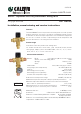

Check valves
In order to prevent undersirable backsiphonage, separate check valves should be installed in systems
with code “521 A” model thermostatic mixing valves (these models do not contain integral check valves
in the hot and cold inlet ports). As a convenience for easier installations, the Caleffi code “521 AC”
model series thermostatic mixing valves include integral check valves in the hot and cold inlet ports.
NOTE TO INSTALLER: DO NOT TEST FIT OR INSTALL CHECK VALVES BEFORE SOLDERING. IF
INSTALLED, REMOVAL WILL REQUIRE DAMAGING THE CHECK VALVE AND IT WILL NO LONGER
BE USABLE.
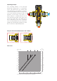
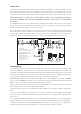
The diagram below shows the order in which everything goes together. Note that the check valves
are installed on the hot and cold inlets, the mixed outlet does not require a check valve. Note that the
O-ring is installed on to the groove of the check valve.
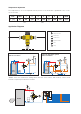
After soldering the tailpieces into place, slide in the check valve into the tailpiece with o-ring going in
first. It will click into place and then the screen will fit into the groove of the tailpiece with the domed
end facing the mixing valve. Once the check valve and screen is installed, use the sealing washer
between the tailpiece and mixing valve body to create a seal and tighten down the union nut.
Commissioning
The special purpose of the thermostatic mixing valve must be commissioned in accordance with
current standards by qualified personnel using temperature measuring equipment. Caleffi codes
521419A, 521519A, and 521619A with integral outlet port temperature gauges provide a time-saving
temperature setting process to get close to the desired temperture. Use of a digital thermometer is
recommended for determining the final setting of the mixed water temperature.
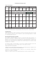
NOTE: Gauge adapters with 2” diameter, 20-210ºF scale, code NA10328 (1/2” sweat), NA10056
(3/4” sweat) or NA10058 (1” sweat) can be separately purchased and field installed to the Caleffi
MixCal series 521 models sold without the integral gauge adapters.
After installation, the valve must be tested and commisioned in accordance with instructions given
below, taking into account current applicable standards.
1) Ensure that the system is clean and free from dirt or debris before commissioning the thermostatic
mixer.
2) It is recommended that the temperature is set using a suitable calibrated digital thermometer.
The valve must be commissioned by measuring the temperature of the mixed water emerging at the
point of use.
3) The maximum outlet temperature from the valve must be set taking account of the fluctuations
due to simultaneous use. It is essential for these conditions to be stabilised before commissioning.
4) Adjust the temperature using the adjusting knob on the valve. For safety reasons. it is advisable to
limit the maximum mixed water temperature to 120ºF in domestic hot water systems.
41 3
1
4
6
2
3
VALVE BODY
UNION NUT, Quantity 3 per valve
UNION WASHER, Quantity 3 per valve
INLET PORT MALE TAILPIECE
WITH INTEGRAL CHECK VALVE
Quantity 2 per valve
INLET PORT CONIC FILTER,
Quantity 2 per valve
7
OUTLET PORT TAILPIECE,
Quantity 1 per valve
5
CHECK VALVE O-RING
2 3 6
6
7
4
2
5
5
(SWEAT TAILPIECE)