
Product Overview
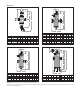
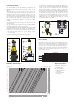

Construction details
The DISCALDIRT air and dirt separator is designed to be
maintained and cleaned without removing it from system
piping.
The automatic air vent, located at the top of the device, has
a long chamber for float movement (2). This prevents any
impurities in the water from reaching the seal seat. The non-
corroding stainless steel pinned linkage and PP float can be
accessed by removing the upper cover (1). The float guide
pin (4) prevents the float from jamming against the inside
housing in non-vertical installations or from boiler residue
buildup.
Unscrew the top part of the casing (3) to clean the entire air
venting system.
The air venting system in both brass and steel DISCALDIRT
air and dirt separators features a pinned float.
Steel DISCALDIRT air and dirt separators with flanged and
threaded connections have an integral side drain port with
shutoff valve, code 538402 FD (5), which has two functions:
1. Air removed while filling the system during system
commissioning
2. Remove debris that float within the air separator.
A separately-sourced drain valve installed to the drain pipe at
the base of the steel DISCALDIRT air and dirt separator (8)
can be used to remove any debris that has settled at the
bottom of the separator, even with the system is in operation.
To inspect the internal element of brass DISCALDIRT air and
dirt separators, unscrew the large dirt separation chamber
(6) with a 26 mm hexagon wrench. The internal element can
be removed for cleaning. Additionally, the brass air and dirt
separator has a lever operated shut-off drain valve code
538402 FD, and hose attachment with plug (7), to drain
accumulated debris as needed.
0.56
G (l/s) (gpm)
(kPa)
2.8
1.4
0.33
0.39
0.44
0.50
0.69
0.83
0.97
1.1
1.25
1.7
1.9
2.2
2.5
3.3
3.9
4.4
5.0
6.9
11
12
5.6
8.3
9.7
14
2”
2 1/2”
28
17
19
22
25
3”
4”
33
39
44
50
56
5”
6”
0.1
0.05
0.09
0.08
0.07
0.06
0.035
0.04
0.045
0.12
0.14
0.16
0.18
0.25
0.3
0.35
0.2
1
0
.
1
0
.
2
0
.
5
0.9
0.8
0.7
0.6
0.12
0.14
0.16
0.18
0.25
0.3
0.35
0.4
0.45
1.2
1.4
1.6
1.8
2.5
3
2
1
0.5
0.9
0.8
0.7
0.6
0.45
0.4
0.09
0.08
0.07
0.06
0.025
0.03
0.
0
2
(ft of water)
∆
P
(ft of water)
100
10
5
20
50
1000
200
500
0.1
0.05
0.09
0.08
0.07
0.06
0.035
0.04
0.045
0.12
0.14
0.16
0.18
0.25
0.3
0.35
0.2
1
0.5
0.9
0.8
0.7
0.6
0.45
0.4
0.025
0.03
0.
0
2
6
7
8
9
12
14
16
18
25
3
0
35
4
0
45
6
0
70
80
90
120
140
160
180
250
400
45
0
300
35
0
600
7
00
8
00
9
00
1.2
1.4
1.6
1.8
2
6
4.5
1.2
1.4
1.6
1.8
2
69
83
97
111
125
2000
1200
1400
1600
1800
4
3.5
5
12”
10”
8”
4.3
4.0
3.5
3.0
2.7
2.2
0.27
0.25
0.22
0.19
0.17
0.14
1”
3/4”
1 1/4”
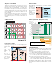
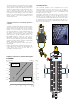
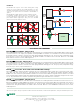
Hydraulic characteristics
Flow Capacity
The fluid velocity at connections for DISCALDIRT 546 and
NA546 series air and dirt separators is recommended to not
exceed 10.0 f/s. Above this speed, heavy internal turbulance
and noise can occur and air and dirt elimination efficiency
begins to fall measurably. Optimal air and dirt separation
performance occurs at fl uid velocities of 4.0 f/s or less. See
the flow capacity chart.
Optimal
(≤4.0 f/s)
FLOW CAPACITY
2”
37.3
2.4
88.8
5.6
87
2 1/2”
63.0
4.0
150.1
9.5
174
3”
95
6.0
227.4
14.3
208
4”
149
9.4
355.3
22.4
324
5”
259
16.3
616.4
38.9
520
6”
380
24.0
903.6
57.0
832
Size
GPM
l/s
GPM
l/s
Cv
Max.
(10.0 f/s)
8”
625
40.0
1,570
100.0
1,109
10”
980
62.0
2,450
155.0
1,387
12”
1,410
89.0
3,530
222.0
1,664
1 1/4”
10.0
0.63
25.0
1.6
40.0
3/4”
8.0
0.5
19.0
1.2
19.1
BRASS STEEL
1”
9.3
0.6
22.1
1.4
32.5
6
5
5
3
2
1
1
3
7
2
4
4
6
5
5
3
2
1
1
3
7
2
4
4
7
6
4
3
2
1
1
3
8
2
7
6
4
3
2
1
1
3
8
2
Replacement parts
Drain valves, items 5 & 7,
code 538402 FD
Air vent assemblies:
- for Brass separators,
code 59829
- for Steel separators,
code 59756