
Submittal Sheet

CALE FFI
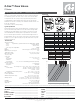
Z-One™ Zone Valves
Z Series
Submittal Data 02917 NA — Issue Date 10/2011
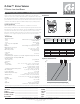
Dimensions
1
3/16
”
2 3/8”
* Terminal block only
B
C
2-way
D
3-way
A
NPT/Inverted are
B
C
A
SAE are
C
3-way
version
B
C
2-way
D
3-way
A
E
3 7/16”
4”
(4 17/32”)*
Sweat
We reserve the right to change our products and their relevant technical data, contained in this publication, at any time and without prior notice. Contractors should request production drawings if prefabricating the system.
Job name ______________________________________
Job location ______________________________________
Engineer ______________________________________
Mechanical contractor ________________________________
Contractor’s P.O. No. ________________________________
Representative ________________________________
Size ________________________________________
Quantity ________________________________________
Approval ________________________________________
Service ________________________________________
Tag No. ________________________________________
Notes ________________________________________
Caleffi North America, Inc. 3883 West Milwaukee Road / Milwaukee, WI 53208
Tel: 414.238.2360 / Fax: 414.238.2366 / www.caleffi .us
© Copyright 2011 Caleffi
(psi) (kPa)
5
00
200
1000
'
p (psi)
G (l/h) (
gpm
)
0.1
1
0.2
0.3
0
.
5
2
3
5
1
0
.5
10
2
5
2
0
1
10
2
3
5
2
0
30
0
.
4
4
0.1
1
0.2
0.3
0
.
5
2
3
5
0
.
4
4
4000
2000
3.5 Cv
3.0 Kv
1/2”
7.5 Cv
6.5 Kv
3/4”-1”
1.0 Cv
0.9 Kv
1/2”
2.5 Cv
2.2 Kv
1/2”
3/4” 3/4” -1 1/4”
5.0 Cv
4.3 Kv
3/4”
1”
ABCD
Connections A B C D E
1/2” sweat 1
5/16
”2
5/8
”
15/16
”1
5/16
”3
1/2
”
3/4” sweat
1
3/8
”2
3/4
”
15/16
”1
1/2
”3
1/2
”
1” sweat
1
11/16
”3
3/8
”
15/16
”1
9/16
”3
11/16
”
1 1/4” sweat
1
13/16
”
15/16
”1
11/16
”3
11/16
”
5/8
”
3
1”NPT
1
13/16
”
5/8
”
3
15/16
”1
11/16
”3
11/16
”
1/2”NPT
15/16
”
1
7/16
”
2
7/8
”
1
1/4
”
1/2
”
3
3/4”NPT
15/16
”1
1/4
”3
11/16
”3
1/16
”1
9/16
”
2-way 1/2” SAE Flare
2
11/32
”4
11/16
”
15/16
”
1/2
”
3
3-way 1/2” SAE Flare
2
11/32
”4
11/16
”
2
1/8
”
1/2
”
3
Inverted flare
1
1/4
”
1/2
”
32
3/4
”1
3/8
”
15/16
”
with adapter (NA61241)
1
1/4
”
1/2
”
3
3
1/2
”
1
3/8
”
15/16
”
Hydraulic characteristics
Typical Specifi cation
Furnish and install on the plans and describing herein, a Caleffi Z-one zone
valve as manufactured by Caleffi . Each zone valve must be designed with
forged brass valve body rated at 300 psi, stainless steel valve stem, and
seals in EPDM. When an auxiliary switch is specifi ed in the 24V actuator,
the zone valve design must include a sealed reed switch. Approved for air
plenum and ducts per UL 1995 section 18. Each zone valve shall be Caleffi
model Z-one series or approval equal. (See product instructions for specifi c
installation information.)
Technical Data
Valve body material:
- Body: forged brass, (optional lead-free brass-IAPMO R&T certifi ed)
- seat: machined brass
- stem: stainless steel
- two o-ring seals and paddle: EPDM
Flow: from 1 to 7.5 Cv
Medium: water and glycol, low pressure steam
Maximum percent of glycol: 50%
Temperature range: 32 to 240°F (0 -115
°C)
Max. static pressure: 15 psi (1 bar) steam
300 psi (20 bar)
Connection:
- sweat: 1/2”, 3/4”, 1” & 1 1/4”
- NPT female: 1/2”, 3/4” & 1”
- SAE fl are: 1/2”
- inverted fl are: 1/2”, 3/4” & 1” sweat fi ttings purchased separately
Actuator material:
- base and cover: polycarbonate
- base plate: aluminum
Motor: -AC voltage: 24V - 120V - 208V - 230V -277V; 50/60 Hz
- Current draw: 24 VAC - 300 mA; 120 VAC; 55 mA;
208 VAC - 30 mA; 230 VAC - 25 mA;
277 VAC - 20 mA
- Terminal block with auxiliary switch: 24 V - class 2 - 5-/60 Hz
Wire lead length: 6” (15 cm), 24 V only 18” (45 cm)
Power requirements: 5 W, 7 VA
Ambient temperature range: 24 V, 120 V: 32 to 104°F
208 V, 230 V, 277 V: 32 to 170°F
Auxiliary switch: 0.0 A min. - 0.4 max., 24 V (24 V actuators)
5.0 A, 250 V (120, 208, 230, 277 V actuator)
Humidity: 95% non-condensing
Full stroke time: - On: <60 seconds
Approvals: UL873, cUL listed & CE
UL 1995 sec. 18: Air plenums & duct
Application
The Z-one, a two-position spring return zone valve, is used in heating and
air-conditioning systems. The Z-one series consist of a Z1 actuator which
is easily attached to a Z2 (2-way) or Z3 (3-way) valve body. Z1 actuator
is equipped with or without auxiliary switch and is UL Listed for plenum
installations. Z1 actuator + Z2 body = Z4 combination and Z1 actuator + Z3
body = Z6 combination.
• US Patent 7,048,251; others pending
Connection size Flow coecient Max. Close-o P
1/2” 1.0 Cv (0.9 Kv) 75 psi (517 kPa)
1/2” - 3/4”
2.5 Cv (2.2 Kv) 50 psi (345 kPa)
1/2” - 3/4”
3.5 Cv (3.0 Kv) 30 psi (207 kPa)
3/4” - 1”
5.0 Cv (4.3 Kv)
25 psi (172 kPa)
3/4” - 1” - 1-1/4”
7.5 Cv (6.5 Kv)
20 psi (138 kPa)