
Operating instructions


© Calibre UK Limited Issue 2.41 04
th
November 2013, W: www.calibreuk.com
T:+44 1274 394125 F: +44 1274 730960 E: techsupport@calibreuk..com 8
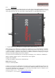
2 – 3G-SDI input 3 – Number intentionally not used
4 – DVI-I output connector (only the digital DVI-D is supported, HDMI 1.3 receivers can be connected
with a DVI/HDMI adapter cable)
5 – TCP/IP port 6 – USB port
7 – RS232 port 8 – Power supply connector
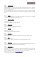
3.3.
Main Menu
The main menu lists 5 sub menus. The 5 sub menus are Output, Colour, Geometry, Enhancement and
System.
On each menu page an Exit menu item is available to leave the menu or submenu. Some adjustments
are not applicable to all signal types or operating modes, in which case those non-applicable functions
will be ghosted and are not accessible via the menus.
All menus have a top status line and a bottom line indicating the firmware revision number. In the status
line the currently selected input channel is indicated and the detected mode is identified. The firmware
revision number displays the revision number of the bootloader behind BL, the revision number of the
firmware behind FW and whether it is a 200S or 210 HQView unit.
To set up your HQView-2xx it is recommended that you follow this procedure:
Choose the correct output mode and parameters to suit your screen or projector.
Set the input levels and features appropriately to optimize the appearance of your image.
Set any other parameters to suit your application.
Note: All Input parameters are specific to your chosen input channel and input signal type, they are not
global to the unit. All Output parameters are global
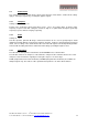
3.4.
Input
The list of available inputs can be scrolled through using the Up and Down keys. The new input is not
selected until the Menu key is pressed.
The list of inputs are: 3G-SDI and Test Pattern.
Test patterns can be generated by HQView-2xx without needing an input connected. When Test Pattern
is selected as the input, the required test pattern can be chosen with the menu navigation up/down keys
when the OSD menu is off.