
User Guide
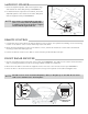
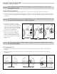
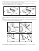
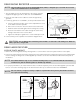

Diagram G2
BRACKET
TAPE
1/4” SCREW
LASER DEFUSER
BRACKET
TAPE
LASER DEFUSER
1/4” SCREW
WITHOUT
HORIZONTAL
TABS
WITH
HORIZONTAL
TABS
3. If utilizing the supplied universal mounting bracket, determine which holes will be used to mount the Laser Defuser to
the vehicle. Remove the unused mounting tabs on the bracket as needed.
4. Apply the supplied double stick tape directly to the Laser Defuser and attach the Laser Defuser to the universal
mounting bracket with the included 1/4” screws. See DIAGRAM G2.
1/4”
SCREW
1/4”
SCREW
5. Install the Laser Defuser to the desired mounting surface using the included 3/4” screws or nylon mounting nuts and
bolts.
6. For proper performance, the Laser Defuser must be mounted perfectly level, facing straight ahead, and as far forward
on the front of the vehicle as possible. See DIAGRAMS G3 and G4.
JAMMING BEAM
Enlarged
View
JAMMING BEAM
LASER DEFUSER
Enlarged
View
NO
CORRECT
LASER DEFUSER
DIAGRAM G3
LASER DEFUSER
Enlarged
View
NO
JAMMING BEAM
LASER DEFUSER
Enlarged
View
CORRECT
DIAGRAM G4
JAMMING BEAM
7. Route the black and clear zip cord wires into the engine compartment either through the grill or under the bumper.
Connect with radar receiver wires per the separate enclosed block diagram sheet.