
Operating instructions


56
21115144_en_310310 © Demag Cranes & Components GmbH
The grip includes the following control and signal devices:
• “Grip occupied” sensor with LED signal display.
If the grip is covered by the operator’s hand, this is indicated by LED (1) lighting
up.
• When the grip is released, the motion is stopped and the brake is applied.
• For activating and de-activating the lifting movement, press the right switch (2)
once.
- LED display (3) off: Switch off.
Lifting/lowering motion not enabled.
- LED display (3) on: Switch on.
Lifting/lowering motion enabled.
The final speeds can be adjusted by programming a parameter in the software
(see chapter 15 “Setting the parameters”).
When the unit is switched on, the right switch (2) is always off. The right switch
(2) is used for stopping and enabling the lifting movement.
• Button left (4) with LED display (5)
The button signal can be looped through as a digital output, i.e. as long as the
button is held down, a 24 V DC signal is output at the relevant output of the
analogue PWM converter.
In general, load movements are only possible if the right switch (2) is switched on
and the grip is covered by the operator’s hand so that the “Grip occupied” indicator
(1) lights up. Otherwise, manual forces do not become effective. A lifting movement
of the load is caused by an upwards movement of the grip (intuitive operation). To
lower the load, move the grip downwards.
The speed of the load movement is proportional to the force with which the grip is
moved upwards or downwards. The measured force is limited at the top and at the
bottom by means of mechanical end stops.
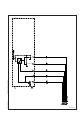
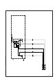
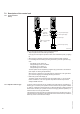
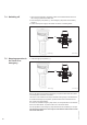
7.2.1 Control switches
D-Grip
(7) “Grip occupied”
sensor
42534244.eps
(1) “Grip occupied” display
(3) “Switch right” display
(2) Switch right
(5) Display
“Button left”
(4) Button left
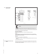
Quick-change coupling
Right-angle
plug
7.2 Description of the control unit
7.2.1.1 Operation with the grip