
User's Manual
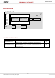
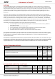
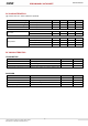

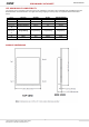
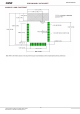

Table Of Contents

This document is subject to change without notice.
Document No: 0020-00-07-00-000 (Issue A)
4
PRELIMINARY DATASHEET
ZB3212F6R4SP2
ANTENNA
The Cortet Mini Modules include an integrated Printed Circuit Board (PCB) trace antenna certified for FCC & IC requirements.
An optional configuration which uses a castellation pin on the module allows the user to connect to an external antenna however
this implementation would require certification by the end user and may not use the CEL FCC ID number on the label. The PCB
antenna employs a topology that is compact and highly efficient. To maximize range, an adequate ground plane must be
provided on the host PCB. Correctly positioned, the ground plane on the host PCB will contribute significantly to the antenna
performance.
For optimum antenna performance, the Cortet Mini Module should be mounted with the PCB trace antenna overhanging the
edge of the host board and ideally in the upper left corner of the host board so that free space is left of the module as opposed to
additional pcb and components. To further improve performance, a ground plane may be placed on the host board under the
module, up to the antenna but not extending under the antenna (a minimum of 1.5" x 1.5" is recommended). The installation of
an uninterrupted ground plane on a layer directly beneath the module will also allow traces to be routed under the layer. Refer to
the application note
Mini Modules Hardware Design Guidelines
for more details. CEL can assist with your PCB layout.
The following are some design guidelines to help ensure optimal antenna performance:
•
The antenna portion of the Mini Module should hang over the host board so that there is not any additional
PCB under the antenna.
•
Never place the antenna close to metallic objects
•
In the final assembly, ensure that wiring and other components are not placed near the antenna
•
Do not place the antenna in a metallic or metalized plastic enclosure
•
Keep plastic enclosures a minimum of 1cm away from the antenna in any direction
Under Industry Canada regulations, this radio transmitter may only operate using an antenna of a type and maximum (or lesser)
gain approved for the transmitter by Industry Canada. To reduce potential radio interference to other users, the antenna type and
its gain should be so chosen that the equivalent isotropically radiated power (e.i.r.p.) is not more than that necessary for
successful communication.
Conformément à la réglementation d'Industrie Canada, le présent émetteur radio peut fonctionner avec une antenne d'un type et
d'un gain maximal (ou inférieur) approuvé pour l'émetteur par Industrie Canada. Dans le but de réduire les risques de brouillage
radioélectrique à l'intention des autres utilisateurs, il faut choisir le type d'antenne et son gain de sorte que la puissance isotrope
rayonnée équivalente (p.i.r.e.) ne dépasse pas l'intensité nécessaire à l'établissement d'une communication satisfaisante.
ABSOLUTE MAXIMUM RATINGS
Description Min Max Unit
Power Supply Voltage
0
3.8
V
Voltage on any 5V Tolerant IO Line -0.3
Min of
5.25 and
VDD+2
V
Voltage on any non-5V Tolerant IO Line
-0.3
VDD+0.3
V
RF Input Power
-
10
dBm
Storage Temperature
-50
150
°C
Reflow Soldering Temperature
-
260
°C
RECOMMENDED OPERATING CONDITIONS
Symbol Parameter Min Typ Max Unit
Power Supply Voltage
2.4 3.3 3.8 V
Frequency 2405
2480
MHz
Ambient Temperature Range -40
85 °C