
User's Manual

MeshConnect™ Module Series
Page 9
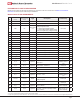
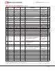
PIN SIGNALS I/O PORT CONFIGURATION
MeshConnect I/O PIN ASSIGNMENTS
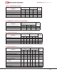
MeshConnect module has 56 edge I/O interfaces for connection to the user’s host board. The MeshConnect Module
Dimensions shows the layout of the 56 edge castellations.
Pin
#
MeshConnect™
Module
MeshConnect™
Extended Range
Module
Type Description Functionality
IC
Pin
#
1 GND GND GND-RF Ground Ground N/A
2 GND GND GND-RF Ground Ground N/A
3 MS1 NC
static control
line
Mode Select, Bit #1. Active Low Internal
Voltage Regulator Enable:
0: Internal Voltage Regulator Enabled
1: Internal Voltage Regulator Disabled, Supply
Analog and Digital Supply Voltages Externally
No connect 14
4 GND GND GND-RF Ground Ground N/A
5 GND NC GND GND Ground 13
6 NC NC NC no connect No connect N/A
7 GND GND GND-Logic Ground Ground 49
8 GND GND GND-Logic Ground Ground 49
9 GND GND GND-Logic Ground Ground 49
10 GND GND GND-Logic Ground Ground 49
11 GND GND GND-Logic Ground Ground 49
12 ACH0 ACH0 Analog Input 1.5V Level Analog ADC0 Input ADC input 8
13 ACH1 ACH1 Analog Input 1.5V Level Analog ADC1 Input ADC input 9
14 ACH2 ACH2 Analog Input 1.5V Level Analog ADC2 Input ADC input 10
15 ACH3 ACH3 Analog Input 1.5V Level Analog ADC3 Input ADC input 11
16 P1_7
(1)
NC digital I/O Port P1.7 Digital I/O 20
17 P1_6
(1)
NC digital I/O Port P1.6 Digital I/O 21
18 P1_4 P1_4 digital I/O
Port P1.4 / QUADZB / Sleep Timer OSC
Buffer Input
digital I/O or
dedicated function
port
22
19 P1_3 P1_3 digital I/O
Port P1.3 / QUADZA / Sleep Timer OSC
Buffer Output / RTCLKOUT
digital I/O or dedicated
function port
23
20 GND GND GND-Logic Ground Ground 49
21 GND GND GND-Logic Ground Ground 49
22 GND GND GND-Logic Ground Ground 49
23 P1_1 P1_1 digital I/O Port P1.1 / TXD1
digital I/O or
dedicated function
port
24
24 VCC_3V VCC_3V Power
3.0V Power supply for Analog Internal
Voltage Regulator
Power Input 7
25 P1_0 P1_0 digital I/O Port P1.0 / RXD1
digital I/O or dedicated
function port
26
26 P3_7 P3_7 digital I/O
Port P3.7 / 12mA Drive capability / PWM3 /
CTS1 / SPICSN
digital I/O with high
current capability
27
27 P3_6 P3_6 digital I/O
Port P3.6 / 12mA Drive capability /PWM2 /
RTS1 / SPICLK
digital I/O with high
current capability
28
Note:
1. Pin used on extended range module to control on board power amplier.
2. Digital 1.5V regulator output. Sources little current. If it is used by the host board, care must be taken to ensure noise is not introduced as it could degrade RF performance.