
User Manual


Mini Module External
A
ntenna Implementation
This document is subject to change without notice.
Document No: 0011-00-16-11-000 (Issue C)
Page 4
COMPONENTS USED IN THE IMPLEMENTATION
The following components specify the requirements for this implementation:
• CEL Module Part Number: ZICM35xSP0-1C is certified with external Antennas "E-2820-CA" & LSR 001-0100"
• CEL Module Part Number: ZICM35xSP2-1C is certified with external antenna "Nearson S181AH-2450S"
• U.FL Connector Part Number: U.FL-R-SMT(10) from Hirose Electric Co. Ltd.
• RP-SMA end launch Part Number: Amphenol 132255RP
• Host Board: FR4 two layer, 0.062” thick with dielectric constant of 4.2 typical. The transmission line between the
module and the U.FL connector should be a straight line with a width of 40 mils, and ground plane spaced 8 mils apart
on the top layer. The bottom layer should be a continuous ground plane under the transmission line. Ground vias
should be included between the module castellation pins and the U.FL connector ground pads to provide a good
RF ground connection.
• Connectors, Cable assemblies, and antennas must be as specified in photos below or equivalent.
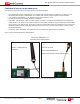
Figure 3 and 4 below illustrates the implementation.
Part Number ZICM35xSP1-1C
External Antenna Implementation
Figure 3. Implementation using connector, cable and external antenna
Antenna: 001-0100
Cable: 095D1ASMARG316
Edge Mount Reverse Polarity SMA Connector
Antenna + Cable Assembly
E-2820-CA