
User manual


User Manual 2253i / 2253iX
2.7 Available Options – iX Series
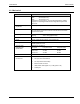
Interface Options
-LAN Ethernet LAN interface connection. RJ45 connector. This option is not
field installable and must be specified at the time of original unit order.
Note: The RS232 interface is disabled if –LAN option is specified.
Test Options
-160 RTCA/DO-160 Revision D and E, EuroCAE test firmware. Revision E
requires use of iXCGui software (included).
-704 Mil-Std 704 Revision D and E test firmware. Revision A, B, C and F
requires use of iXCGui software (included).
-704F Mil-Std 704 Revisions A through F test firmware.
-A350 Airbus A350 / ABD0100.1.8.1 test software. Requires use of iXCGui
software (included).
-ABD Airbus ABD0100.1.8 test software. Requires use of iXCGui software
(included).
-AMD Airbus A400M Directive AMD24 test software. Requires use of iXCGui
software (included).
-B787 Boeing B787-0147 test software. Requires use of iXCGui software
(included).
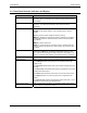
Misc. Options
-ABL Atlas Based Language Extension. The ABLE command language
provides bus compatibility with 9012 PIP controllers.
-EXS External Sync Input. This option changes the external trigger input to an
external sync input. The output frequency will be synced to the square
wave TTL level sync signal provided.
-EXT External Signal Input. This option allows a 0-5Vrms AC signal to be used
as the oscillator signal. In this mode, the AC power source acts as an AC
amplifier. No programmable current limit is available and the output
frequency of 1000 Hz should not be exceeded. Mutually exclusive with –
RPF and –RPV options.
-LKM Clock and Lock Master. Enables synchronizing outputs of two iX AC
sources. This mode supports a frequency range of 16 to 819 Hz.
The –LKM applies to the master unit. This option is not field installable
and must be specified at the time of original unit order.
-LKS Clock and Lock Auxiliary. See -LKM for details. The –LKS applies to the
auxiliary unit. (See Notes, see section 3.9.) This option is not field
installable and must be specified at the time of original unit order.
This option is mutually exclusive with the –RPF option.
-MODE Mode option allows all three amplifier phase outputs to be combined on
phase A output terminal. No external switching or reconnection to the
load is required.
-RMS Set of 2 Rack mount slides. (Left and Right) Recommended to mount
chassis in 19-inch instrument cabinet.
-RPV Remote programming voltage. DC voltage input 0 to 10 VDC for 0 to full-
scale output voltage programming. Mutually exclusive with –EXT option.
-RPF Remote programming frequency. DC voltage input 0 to 10 VDC or 0 to 5
VDC for 0 to 800 Hz out
p
ut f
r
e
q
uenc
y
p
ro
g
rammin
g
. In
p
ut im
p
edance is
California Instruments 27