
User manual

User Manual 2253i / 2253iX
6. Calibration
The Routine Calibration should be performed every 12 months. Non-routine Calibration is only
required if a related assembly is replaced or if the periodic calibration is unsuccessful. Calibration of
the i/iX system can be performed from the front panel or over the bus. This section covers calibration
from the front panel.
6.1 Recommended Calibration Equipment
Digital Multimeter: Fluke 8506A, 8508 or equivalent.
10 mOhm Current Shunt: Isotek Model RUG-Z-R010-0.1.
Load Various power load resistors or a resistive load bank will be needed.
Size of epends on model.
perform the current measurement calibration near full scale. Current
measurement calibration should be done on the lowest available
voltage range.
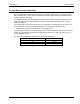
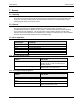
The accuracy and value of the load resistor is not critical as long as
the current drawn is sufficient to operate the AC Source in the upper
current range (80-100 %). Suggested values of load bank settings are
Bank:
the load bank d A load is required to
shown in Table 6-1.
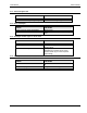
6.2 Calibration Screens
The calibration screens for output or measurement calibration can be selected from the MENU scree
es to toggle to select the CALIBRATION screen.)
een press the MENU key several times to select MEAS CAL. Then
bring up the PASSWORD screen. To prevent unauthorized access to
st be entered to access any calibration screen. The calibration
ual to the high voltage range limit. This value is 300.
sing the shuttle or the keypad. Once the correct value is set, press the
ration screens remain accessi
n.
(Press MENU button several tim
To select the CALIBRATION scr
press the ENTER key. This will
calibration data, a password mu
password is a numeric value eq
The password can be entered u
ENTER key. Once set, the calib ble until the power source is powered
d
by the ENTER key to re-engage
To select the MEASUREMENT
select the MEAS CAL entry. If a up, no
password is needed. Otherwise
6.3 Measurement Calibration
down. If you leave the calibration screen and return, toggle the value up or down and back, followe
the calibration mode.
CALIBRATION screen, follow the same steps as outlined above and
nother CALIBRATION screen has been accessed since power-
, enter the password as indicated above.
The i/iX Series controller measu
waveforms on each available output phase. This data is subsequently processed and used to
calculate all measurement parameters such as VRMS, IRMS, Power, VA, and Frequency etc. To
calibrate all measurements, only the voltage and current measurement need to be calibrated
specifically. All other measurements are derived from these.
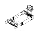
Connect the test equipment to the power source.
Note: The Fluke 8506A or 8508 Digital Multi meter (or higher AC accuracy DMM) must be used
res voltage and current by digitizing both voltage and current
for the following calibration. The DMM must be set to the AC HI ACCUR mode for all
AC measurements.
California Instruments 94