Revision C Copyright 1995, 1996 by California Instruments. All rights reserved.
L-Series and FCS-18- Graphical User Interface User Manual (This page intentionally left blank) 2 California Instruments Rev C - June 1996
L-Series and FCS-18 Graphical User Interface User Manual LIMITED WARRANTY California Instruments believes the information contained in this manual is accurate. This document has been carefully reviewed for technical accuracy. In the event that technical or typographical errors exist, California Instruments reserves the right to make changes to subsequent editions of this document without prior notice to holders of this edition. The reader should consult California Instruments if errors are suspected.
L-Series and FCS-18- Graphical User Interface User Manual (This page intentionally left blank) 4 California Instruments Rev C - June 1996
L-Series and FCS-18 Graphical User Interface User Manual Table of Contents 1. Introduction ..................................................................................................................................................... 9 1.1 About this program ................................................................................................................................... 9 1.2 About this manual..........................................................................................
L-Series and FCS-18- Graphical User Interface User Manual 7.1.1 Transient data Entry fields ..............................................................................................................48 7.1.2 Error checking .................................................................................................................................50 7.2 Transient types ......................................................................................................................................
L-Series and FCS-18 Graphical User Interface User Manual 13.1.3 Decimal separator......................................................................................................................... 96 13.1.4 To resolve problems 2 and 3, follow these steps:......................................................................... 96 13.2 Interface problems ............................................................................................................................. 102 13.2.
L-Series and FCS-18- Graphical User Interface User Manual (This page intentionally left blank) 8 California Instruments Rev C - June 1996
L-Series and FCS-18 Graphical User Interface User Manual 1. Introduction 1.1 About this program The L Series Graphical User Interface program - LSGUI - was developed as a companion product to the California Instrument line of AC power sources. It’s main purpose is to provide a soft front panel to the instrument when connected to a PC through the IEEE-488 bus interface. Additional benefits are obtained from using the PC as a control interface.
L-Series and FCS-18- Graphical User Interface User Manual 1.3 Software version From time to time, it may be necessary to release a new version of the LSGUI software to fix bugs and or add new features and capabilities. This will result in the decimal portion of the version number being increased. In this case, it is unlikely that a new user manual would be required. Addendum’s and changes to this manual will be provided in the form of a readme.txt file on the distribution disk.
L-Series and FCS-18 Graphical User Interface User Manual 2. Requirements To successfully install and operate the LSGUI program, you will need the following equipment : L-Series AC power source. Supported models are : 751L 6000L 1501L 9000L 1503L 12000L 2000L 13500L 2750L 18000L1 4500L • • • • -P or -PT programmable controller. Manual controller (Type -M) equipped L-Series AC sources can not be operated by this program. Contact California Instruments for information on upgrading to a -P or -PT controller.
L-Series and FCS-18- Graphical User Interface User Manual 3. Setup and Installation This section covers installation of the LSGUI from the distribution disk to the user’s PC. Make sure the PC is capable of running Windows 3.1™ Enhanced mode or equivalent with at least 4 Mbyte of memory and 2 Mbyte of available hard disk space. 3.1 Connecting an L-Series AC source to PC Connect the L-Series AC source to the PC using a suitable IEEE interface cable.
L-Series and FCS-18 Graphical User Interface User Manual 3.3 Installed files The installation program will install the following files in the directories specified. Note that files with the same name that already exists in these directories will be overwritten as part of the installation process. As long as the files being overwritten are of an older date (previous version), this should not cause any problems.
L-Series and FCS-18- Graphical User Interface User Manual 3.4 Manual installation If the installation program is unable to complete the installation process successfully, you may attempt to manually install the files listed in section 3.3. All files on the distribution diskette are compressed so they cannot be copied directly to the hard disk. Instead, use the “expand.exe” program that is located in the DOS directory of your PC.
L-Series and FCS-18 Graphical User Interface User Manual 3.5 Software registration We encourage you to send in the software end-user registration form located on the next page. Only registered users will be informed of software updates and bug fixes that may be released from time to time. Please mail the completed end-user registration form to the following address: California Instruments Corporation Attn: Customer Satisfaction Department 9689 Towne Centre Drive San Diego, CA 92121 U.S.A.
L-Series and FCS-18- Graphical User Interface User Manual (This page intentionally left blank) 16 California Instruments Rev C - June 1996
L-Series and FCS-18 Graphical User Interface User Manual California Instruments Corporation Software End-user Registration Form Complete and submit to: California Instruments Corporation Attn: Customer Satisfaction Department 9689 Towne Centre Drive San Diego, CA 92121 United States of America End-user information Company _________________________ Division __________________________ Contact _________________________ Title __________________________ Department _________________________ Address _____
L-Series and FCS-18- Graphical User Interface User Manual (This page intentionally left blank) 18 California Instruments Rev C - June 1996
L-Series and FCS-18 Graphical User Interface User Manual 4. User Interface aspects This chapter reviews the various user interface aspects of the LSGUI program. It covers menus and mouse operation. Experienced Windows users can skip sections 4.4 and 4.6. 4.1 Starting the LSGUI Use the mouse to double click on the LSGUI icon (). If you are not comfortable double clicking with a mouse, you can also click on the icon once to select it, and then press the Enter key.
L-Series and FCS-18- Graphical User Interface User Manual 4.3 Main program window The LSGUI software is operated through a series of modal dialog boxes or screens that are all accessed from the main menu bar. The main menu bar is shown along the top edge of the main program window. Located directly below the main menu bar is the toolbar or buttonbar. The toolbar provides mouse click shortcuts for the most commonly accessed menus and sub-menus.
L-Series and FCS-18 Graphical User Interface User Manual 4.4 Menu Structure The main menu provides access to all windows and screens available in the LSGUI program. It is organized in logical groups that cover different aspects of AC source control. The purpose of each menu group is discussed briefly in this chapter. More detailed information can be found in the relevant chapters that follow. Figure 2 provides a flowchart of all available menus and sub-menus in the LSGUI program.
L-Series and FCS-18- Graphical User Interface User Manual 4.4.1 File menu The File menu allows access to instrument setup files that are stored in setup files. It also provides the means to close and exit the program. The following File Menu entries exist : Submenu New Open... Save Save As... Exit 22 Purpose Resets all setup information to default values. If an actual L-Series is connected to the PC, hardware configuration data remains unchanged. Opens the File Open dialog box.
L-Series and FCS-18 Graphical User Interface User Manual 4.4.2 Configuration menu The configuration menu allows the user to change the configuration of the LSGUI program and the IEEE-488 interface. It also provides access to the L-Series hardware configuration screen. Note that the L-Series hardware configuration cannot be changed by the end-user. It is set at the factory at the time of shipment. You can however save the configuration data to disk in case the non-volatile memory contents ever gets lost.
L-Series and FCS-18- Graphical User Interface User Manual 4.4.3 Source menu The source menu provides front panel control of the L-Series. Available sub-menus are : Submenu Initialization... Steady State... Transients... 24 Purpose Opens the Source Initialization window. Initialization parameters for frequency, voltage (all phases in a three phase system), current limit and voltage range can be set from the Initialization window.
L-Series and FCS-18 Graphical User Interface User Manual 4.4.4 Measurement menu The measurement menu provides only two sub-menus. They are : Sub-menu Show... Data File... Rev C - June 1996 Purpose Opens the measurement window. This is a non-modal window which can be left open at all times. The measurement window provides constant readouts of up to 19 parameters. Different screen colors are used to indicate different phases.
L-Series and FCS-18- Graphical User Interface User Manual 4.4.5 Options menu The options menu provides functions that logically cannot be grouped under any other main menu heading. Specifically, the following three submenus are available: Submenu Show Toolbar Save Configuration File... Restore Configuration File... 26 Purpose This menu entry provides a toggle function to enable or disable the toolbar at the top of the main program window.
L-Series and FCS-18 Graphical User Interface User Manual 4.4.6 Applications menu The Applications menu may or may not appear when running the LSGUI program. Its presence is determined by the availability of the MIL-STD-704 and RTCA/DO-160 application options in the connected L-Series AC source. If neither option is detected, the Applications menu will not be shown at all.
L-Series and FCS-18- Graphical User Interface User Manual 4.4.7 Help menu The Help menu is a standard menu found in all Windows applications. It provides access to on-line context sensitive help information. The following sub-menus are available : Contents... Opens the LSGUI help file at the contents page. From the contents page, a selection of topics is available. Search for Help on Opens the LSGUI help file in the Search dialog mode. Use this sub-menu to look for help on a specific topic.
L-Series and FCS-18 Graphical User Interface User Manual 4.5 Selecting menu items with the mouse To select any menu item using the mouse, move the mouse pointer to the desired entry and press the left mouse button. (Click) 4.6 Selecting menu items using the keyboard To select any menu using the keyboard, hold down the ALT key and press the letter of the menu item that is underlined. Thus, to select the “File” menu item, hold down the ALT key and press the letter “F”.
L-Series and FCS-18- Graphical User Interface User Manual 4.7 Using the Toolbar The toolbar provides a convenient shortcut for mouse savvy operators. Clicking on each of the toolbars icons will cause the corresponding menu and sub-menu to be selected at once. The following toolbar icons and their corresponding menu equivalents are provided : Icon Menu equivalent Description 30 File-New Resets all setup information to default values.
L-Series and FCS-18 Graphical User Interface User Manual Icon Rev C - June 1996 Menu equivalent Description Source-Steady State... Opens the Steady State soft front panel. This control panel allows all output parameters of the L-Series to be set using the mouse. This window can be left open at all times. The state of this window (opened or closed) is reflected by the icon on the toolbar. If the icon is depressed, the window is open. Open windows can be minimized or may be hidden behind other windows.
L-Series and FCS-18- Graphical User Interface User Manual 4.8 Status bar The bottom edge of the main program window contains the status bar. Information concerning the LSGUI program status is displayed here. The status bar also contains a rectangular LED style indicator for the IEEE-488 interface. If this indicator is on (yellow), an L-Series power source is present on the IEEE bus. When the LSGUI is in simulation mode, this LED will be off.
L-Series and FCS-18 Graphical User Interface User Manual 5. L-Series Hardware Configuration This chapter reviews the operation of the three available configuration screens.
L-Series and FCS-18- Graphical User Interface User Manual 5.1 Model Number and Controller type selection screen The configuration model screen lists all available L-Series models and controller types. In normal operation mode - (L-Series connected to PC) this screen is used for display purposes only. No changes can be made to the active model number and controller type. When in simulation mode, changes made to the selected model number and controller type will take effect when the button is clicked.
L-Series and FCS-18 Graphical User Interface User Manual 5.2 System Settings screen The system settings screen is provided primarily for informational purposes. None of the fields and options shown on this screen can be changed by the user. This is because hardware configurations are based on the actual L-Series unit found at the specified IEEE address. The calibration password entry field can be used by qualified calibration personnel to access the output calibration and measurement calibration screens.
L-Series and FCS-18- Graphical User Interface User Manual 5.3 IEEE Interface screen The IEEE Interface screen is used for three different purposes. 1. As a means of changing the IEEE address used to connect to the LSeries power source. Only one L-Series power source is supported at a time in this version of the LSGUI. This does include however multi-box LSeries units operated from a single -P or -PT controller.
L-Series and FCS-18 Graphical User Interface User Manual 6. Source control The Source screens provide the type of interactive instrument control normally associated with instrument front panels. There are three source control screens that each affect a different area of operation of the L-Series AC source. With the exception of the Steady State screen, the Source control windows are modal meaning only one of them can be opened at a time and they must be closed before moving to another menu or window.
L-Series and FCS-18- Graphical User Interface User Manual 6.1 Source Initialization Source Initialization covers those source output parameters that can be initialized to specific values at power up. These values take effect as soon as the AC source is powered up and remain in effect until changed from the front panel or over the IEEE interface. The initialization values are retained in non-volatile memory.
L-Series and FCS-18 Graphical User Interface User Manual 6.2 Steady State control The steady state control panel is the normal control panel for changing source settings in real time. Since it is a crucial element of the LSGUI program, it is a non-modal window. This means it can be left open at all times as long as the LSGUI program is running. To free up screen space, you may minimize the steady state control screen.
L-Series and FCS-18- Graphical User Interface User Manual 6.3 Steady state execution modes The steady state control panel can be used in one of two operating modes. These modes are Immediate or Update and can be found on the right hand side in the Execution area. 6.3.1 Update mode If the control panel is in the Update mode (default mode when the window is opened), changes made to any of the controls have no effect until the key is pressed.
L-Series and FCS-18 Graphical User Interface User Manual 6.4 Frequency control The frequency can be changed by moving the slider control at the top of the screen left or right. The minimum and maximum frequency limits are determined by the hardware settings of the L-Series unit connected. The frequency value can also be typed in from the keyboard when the cursor is in the frequency edit box. The frequenc y value slider control can be used to change the frequency in three different ways : 1.
L-Series and FCS-18- Graphical User Interface User Manual 6.5 Voltage Range selection If the connected L-Series unit is equipped with dual voltage range capability, the voltage range option box will be enabled and the selected voltage range will be shown. This control can be used to toggle between the two voltage ranges. The values shown for each range are based on the hardware configuration settings. Note : changing the voltage range will cause the output voltage for all phases to be set to zero volts. 6.
L-Series and FCS-18 Graphical User Interface User Manual 6.6 Phase mode control If the connected L-Series is a three phase model and is equipped with the MODE option, the phase mode control will be enabled. This control consists of two option boxes, one for single phase mode and one for three phase mode. Clicking on Single ø will put all three amplifiers in parallel and provide all power available to phase A. Clicking on Three ø will use one amplifier per phase for three phase operation.
L-Series and FCS-18- Graphical User Interface User Manual 6.7 Output relay control The output relay control allows the output relay to be opened or closed. When the output relay is opened, the voltage is programmed back to zero volts to avoid hotswitching the relay. When the relay is closed, the voltage is programmed back to its original value. When the steady state control panel is opened, the status of the output relay is reflected in this area. 6.
L-Series and FCS-18 Graphical User Interface User Manual 6.9 Phase controls Phase controls affect one, two or three phase parameters at once. The phases affected can be selected using the check boxes located next to each phase letter. Changes made only affect those phases which have a check mark. This allows changes to be made to an individual phase as well as for multiple phases at once. If the connected L-Series is a single phase unit only, phase B and C controls are always disabled.
L-Series and FCS-18- Graphical User Interface User Manual 6.9.3 Phase angle control Phase angles can be set for each phase individually. Note that setting the phase angle for phase A with an internal clock reference has no effect as phase A will be used as the reference. Phase angle for phase A is only meaningful if external sync is used. External sync is not supported by the LSGUI program at this time. 6.9.
L-Series and FCS-18 Graphical User Interface User Manual 7. Transients This chapter covers transient programming. Transients are an effective way of generating common disturbances found on power lines. The L-Series AC sources are equipped with sixteen non volatile transient memory registers. The transient programming screen is used to specify transient types and parameters for each register. Once downloaded, transients can be executed starting from any of the sixteen registers.
L-Series and FCS-18- Graphical User Interface User Manual 7.1 Transient data entry The transient screen provides a grid like data entry screen that is used to specify transient type and parameters for each of the sixteen transient registers. (numbered 0 through 15) 7.1.1 Transient data Entry fields This data entry grid consists of nine columns representing the following fields: Register Trans.Type Goto V 48 Number of the transient register that will be used to hold the transient information.
L-Series and FCS-18 Graphical User Interface User Manual Final V Goto F Final F Start ø Delay (s) Link to: Rev C - June 1996 Delay field. Whether it represents a sag or a surge will depend on the steady state voltage present at the time the transient is executed. Final voltage value. This is the voltage present at the end of the transient delay. For voltage steps, this field is disabled since the Final V would be identical to the Goto V value anyway. Initial frequency value.
L-Series and FCS-18- Graphical User Interface User Manual 7.1.2 Error checking As data is entered into each field, error checking is performed when the focus is moved from one field to the next. If appropriate, an error message will occur indicating the nature of the mistake. At the same time, the erroneous value is replaced with a default. To fix the error, accept the default or move the cursor back to the previous field (press Shift-Tab) and enter the correct value.
L-Series and FCS-18 Graphical User Interface User Manual 7.2 Transient types The LSGUI program supports several different transient types. Each transient type and its parameters are described in more detail in this section. The available transient types are : no. 1. 2. 3. 4. 5. 6. 7. 8. 9. 10.
L-Series and FCS-18- Graphical User Interface User Manual 7.2.1 Voltage dropout transient Voltage dropout transients will cause the output voltage to drop to zero volt starting at the phase angle specified in the phase ø field for a duration specified in the Delay (s) field. The delay value can range from 1 ms to 9999 seconds. At the end of the dropout, the output value is set to the value specified by the Final V field.
L-Series and FCS-18 Graphical User Interface User Manual 7.2.2 Voltage step transient Voltage step transients will cause the output voltage to go to the value specified in the Goto V field starting at the phase angle specified in the phase ø field for a duration specified in the Delay (s) field. The delay value can range from 1 ms to 9999 seconds. At the end of the delay period, the output value will still be at the Goto V value so there is no need to specify a Final V value.
L-Series and FCS-18- Graphical User Interface User Manual 7.2.3 Voltage surge or sag transient Voltage surge and sag transients will cause the output voltage to go to the value specified in the Goto V field starting at the phase angle specified in the phase ø field for a duration specified in the Delay (s) field. The delay value can range from 1 ms to 9999 seconds. At the end of the delay period, the output value will still be set to the value specified by the Final V field.
L-Series and FCS-18 Graphical User Interface User Manual 7.2.4 Voltage sweep transient Voltage sweep transients will cause the output voltage to change gradually from the Goto V value to the Final V value over a period of time specified by the Delay field. The delay value can range from 1 ms to 9999 seconds. At the end of the delay period, the output value will remain at the value specified by the Final V field.
L-Series and FCS-18- Graphical User Interface User Manual 7.2.5 Frequency sweep transient Frequency step transients will cause the output frequency to go to the value specified in the Goto F field starting at the phase angle specified in the phase ø field for a duration specified in the Delay (s) field. The delay value can range from 1 ms to 9999 seconds. At the end of the delay period, the output frequency will remain at the Goto F value so there is no need to specify a Final V value.
L-Series and FCS-18 Graphical User Interface User Manual 7.2.6 Frequency surge or sag transient Frequency surge and sag transients will cause the output frequency to go to the value specified in the Goto F field starting at the phase angle specified in the phase ø field for a duration specified in the Delay (s) field. The delay value can range from 1 ms to 9999 seconds. At the end of the delay period, the output value will still be set to the value specified by the Final V field.
L-Series and FCS-18- Graphical User Interface User Manual 7.2.7 Frequency sweep transient Frequency sweep transients will cause the output frequency to change gradually from the Goto F value to the Final F value over a period of time specified by the Delay field. The delay value can range from 1 ms to 9999 seconds. At the end of the delay period, the output frequency will remain at the value specified by the Final F field.
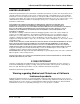
L-Series and FCS-18 Graphical User Interface User Manual 7.2.8 Voltage and Frequency sweep transient. The VF Sweep transient is a compound transient that combines a Voltage and a Frequency sweep into a single register step. When executed, both voltage and frequency change simultaneously. Refer to section 7.2.4 and section 7.2.7 for details on separate voltage and frequency sweeps. 45 V rms 135 V rms 70 ms Voltage and Frequency transient from 135 V to 45 V and 50 Hz to 300 Hz executed over a 70 ms period.
L-Series and FCS-18- Graphical User Interface User Manual 7.3 Linking transient registers together The ‘Link to:’ field will accept any register number from 0 through 15. If a Link is set to a register which Trans.Type field is ‘Empty’, an error message will appear when the transient register contents is downloaded. The following transient program, will result in the error message shown below: The error is shown to be in register 1 where a Link is made to register 2.
L-Series and FCS-18 Graphical User Interface User Manual 7.4 Transient phase selection The same transient program can be used for one phase, two phase or all three phases of a three phase system. The Phase selection check boxes located in the bottom right corner of the Transient screen are used for this purpose. If the connected L-Series unit is a single phase instrument or a three phase unit with the mode option set to single phase, these controls will be disabled and only phase A will have a check mark.
L-Series and FCS-18- Graphical User Interface User Manual 7.5 Downloading transient registers Once all relevant transient information has been entered in the data fields, the contents of all registers can be downloaded to the L-Series unit. key located on the This is accomplished by clicking on the right hand side of the transient screen. If an L-Series is connected to the PC, the contents for all registers with a transient type other than Empty will be transferred to the instrument.
L-Series and FCS-18 Graphical User Interface User Manual 7.6 Managing multiple transient programs Multiple transient program lists can be saved to disk for later use. This allows the user to create his or her own library of commonly used transient programs. 7.6.1 Saving transient lists When the button is clicked, a file dialog box will appear prompting the user to supply a transient program file name. Any eight character name can be used.
L-Series and FCS-18- Graphical User Interface User Manual 7.6.3 Erasing transient lists To erase the entire contents of the data entry area, the user has two options. Either create a transient list file consisting of only Empty transient types and save it on disk with a descriptive name such as “EMPTY.TLS”. Anytime the data present needs to be erased, load the EMPTY.LST file. Alternatively, the button, located in the bottom right corner can be used.
L-Series and FCS-18 Graphical User Interface User Manual 7.6.4 Transient list file extension Transient list files always use the “.TLS” extension. This extension is reserved for this purpose and no other files using the same extension should be stored in the same subdirectory as used to hold transient list programs. Transient list files are stored in simple ASCII formats to facilitate documentation and transfer of transient list programs through email systems.
L-Series and FCS-18- Graphical User Interface User Manual 7.7 Transient execution Transient execution can be started by clicking on the button. The register shown in the “Start from Reg:” drop down list will be the first one executed. Select the desired register number before pressing the button. If this register is linked to other registers, execution will proceed according to the link sequence. (Refer to section 7.3) button can be used to stop transients in progress.
L-Series and FCS-18 Graphical User Interface User Manual 8. Measurements This chapter discusses the various measurements that are available from the L-Series. Measurements can be displayed on screen and stored to disk. The ability to use the LSGUI program as a DDE server is also discussed. Examples are provided for using collected data in spreadsheet programs such as Excel.
L-Series and FCS-18- Graphical User Interface User Manual 8.1 Selecting measurements The L-Series can provide up to nineteen parameters in case of a three phase system or seven in case of a single phase system. Each parameter takes a certain amount of time to obtain. If all nineteen parameters are requested, the total measurement time can approach 5 seconds.
L-Series and FCS-18 Graphical User Interface User Manual 8.2 Measurement modes Two measurement modes are supported by the LSGUI program. They are both selected from the measurement window using the Mode field located on the right hand side of the window. The following modes are available : Run Once mode This mode will cause all measurements to button is be taken once when the clicked. Once a cycle has been started, it will run through completely, even if the button is clicked.
L-Series and FCS-18- Graphical User Interface User Manual 8.3 Stay on top feature The measurement window is a non-modal window (refer to section 4.9) and can thus be left open at all times while the LSGUI program is running. To use the measurement window for monitoring load characteristics while working in other windows programs, the stay on top feature can be useful as it allows you to switch to other Windows programs without loosing sight of your measurements.
L-Series and FCS-18 Graphical User Interface User Manual 8.4 Data logging The data logging feature permits measurement data to be written to disk for archiving, documentation and analysis purposes. This capability can be turned on or off by setting a check mark at the bottom of the measurement window at the “Log data every..” position. Once enabled, measurements are taken at the interval rate displayed in the text box at the bottom of the measurement window. The minimum logging interval time is 5 seconds.
L-Series and FCS-18- Graphical User Interface User Manual 8.4.2 Selecting the File Mode Two file modes are supported, append and overwrite. Append mode is useful for accumulating test data on the same unit under test but broken up into multiple test sessions. Overwrite is useful when old data is no longer needed or has become invalid and needs to be replaced while maintaining the same file name.
L-Series and FCS-18 Graphical User Interface User Manual 8.4.4 Data file comments A comment line can be added to the data file for future reference. This can be useful when trying to analyze data taken in the past. The comment line will be added at the top of the data acquisition file unless the selected file already exists in which case any new comment entered here will be ignored. 8.4.5 Data File Format Data files are saved in plain ASCII text using the common CSV format.
L-Series and FCS-18- Graphical User Interface User Manual A sample data file is shown here as an example. This example uses the serial number timestamp format. Only 8 data records are shown. Phase B and C measurements were disabled and therefore do not show. #1995-08-24 15:30:27#,"User Comment line goes here" "Time_serial","F","V(A)","I(A)","°(A)","W(A)","VA(A)","PF(A)" 34935.64615,60.0,125.2,0.21,0.00,28,26,1.000 34935.64620,60.0,125.2,0.30,0.00,28,38,1.000 34935.64626,60.0,125.2,0.21,0.00,27,26,1.
L-Series and FCS-18 Graphical User Interface User Manual 8.5 Using a spreadsheet program The data file format for data logging files was chosen to be easily used by other programs. As such, it can be loaded directly by programs such as excel. The comma separated fields will automatically be entered in individual columns with each row representing one measurement cycle. Once imported into Excel, analysis and graphical trend data displays are easily generated. Refer to your Excel documentation for details.
L-Series and FCS-18- Graphical User Interface User Manual 8.6 Dynamic data exchange Dynamic data exchange (DDE) is a standard Windows 3.1™ mechanism for sharing information between different windows applications. The LSGUI uses DDE to make measurement data available to other windows programs as it is being reported by the L-Series unit. No specific action is required by the user to enable DDE as it is always active. The LSGUI acts as a DDE server making data available for other programs to use.
L-Series and FCS-18 Graphical User Interface User Manual 9. Applications This section covers the optional MIL-STD-704 and RTCA/DO-160 tests that are available for the L-Series units. If your unit is not equipped with any of these options, the Applications menu will not be visible. Only the options that are installed in the L-Series unit connected to the PC will be shown on the Applications menu. (refer to section 4.4.6).
L-Series and FCS-18- Graphical User Interface User Manual 9.2 RTCA/DO-160 The RTCA/DO-160 test option provides a large set of standard tests designed to verify compliance to the RTCA/DO-160 standard. Selecting this menu item will provide a dialog box with a set of option boxes allowing the user to choose all tests or any subset of the entire test suite. Once a selection has been made, the user can start test execution by clicking on the Start button in the Test Execution section of the window.
L-Series and FCS-18 Graphical User Interface User Manual 10. Calibration This section covers L-Series calibration using the LSGUI program as a support tool. 10.1 Calibration support features L-Series instruments require regular calibration to maintain performance specifications. As a general rule, annual calibration of the output and the measurement system is recommended. The LSGUI program, while not specifically designed as a calibration program, can be used to assist with the calibration process.
L-Series and FCS-18- Graphical User Interface User Manual 10.3 Output Calibration Output calibration is used to enhance the accuracy of the programmed output voltage. A 5½ digit digital true rms AC multimeter is required to perform this calibration procedure. Recommended equipment is Fluke model 45, Fluke model 884X or HP 34401A. There is a difference in procedure for each of the two controller types used in the L-Series. Both are covered here. 10.3.
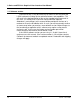
L-Series and FCS-18 Graphical User Interface User Manual 10.3.2 PT controller PT controller equipped L-Series power source require some internal adjustments in order to perform an output calibration. The location of these adjustment points differs depending on the model number used. The on line Help system shows the location of the adjustment points referenced in the calibration procedure.
L-Series and FCS-18- Graphical User Interface User Manual Back panel R105 A R105 B R48 R105 (Top view) C R47 R39 current limit boar d R111 R110 R109 Front panel Location of output calibration adjustments for PT controller based LSeries power source.
L-Series and FCS-18 Graphical User Interface User Manual 10.4 Measurement Calibration Measurement calibration is recommended on an annual basis to ensure the measurement results are within published specifications. All measurement calibration can be performed without removing the covers. Measurement calibration coefficients are used to adjust each parameter readout. Measurement calibration functions are only accessible if the correct calibration password is entered in the System settings window.
L-Series and FCS-18- Graphical User Interface User Manual Calibration procedure: Connect the DMM AC input terminals to the sense lines for phase A of the AC power source and select a measurement range that will accommodate 135 VAC. (typically 200 V range). Enter the readout in the Voltage value field for phase A. Repeat for phase B and C if available. Repeat previous steps for current and power and enter all values accordingly. Once all measurement values have been entered, press the ‘Update’ button.
L-Series and FCS-18 Graphical User Interface User Manual 11. Managing L-Series hardware configuration data Each L-Series units maintains a set of configuration constants in nonvolatile memory. When the LSGUI program is launched, it queries the connected L-Series unit for this data. If no unit is connected , the program enters into a simulation mode. A remote possibility exists that the configuration data that is retained in non-volatile memory is lost due to unforeseen circumstances.
L-Series and FCS-18- Graphical User Interface User Manual 11.2 Restoring configuration data To restore configuration data in case of non volatile memory loss, select the “Restore Configuration File...” entry from the “Options” menu. This will bring up the following dialog box. The number of configuration data files shown may be less depending on the number of different L-Series power sources you own. There can be only one configuration data file for each instrument. Select the correct serial number.
L-Series and FCS-18 Graphical User Interface User Manual 11.3 Obtaining lost configuration data In the event you did not save a configuration file for an L-Series unit, you may obtain a disk with the correct configuration file for your unit from California Instruments' Customer Satisfaction Department. Contact California Instruments and provide the model number and serial number of the affected L-Series unit. A 3.5 inch disk will be mailed to you which contains the correct configuration data.
L-Series and FCS-18- Graphical User Interface User Manual (This page intentionally left blank) 88 California Instruments Rev C - June 1996
L-Series and FCS-18 Graphical User Interface User Manual 12. File Formats This section describes the various file formats of the files used by the LSGUI program. Normally, there is no reason a user would have to access these files other than from the LSGUI program itself. In this case, the file formats are transparent and there is no need to know their details. In the unlikely event that a user wants to manually edit any of these files, the format needs to be known.
L-Series and FCS-18- Graphical User Interface User Manual 12.1 Setup files (.stp) Setup files are given the default extension 'stp' which is short for setup. Setup files have only limited use in the LSGUI program as most of the setting for the program are dictated by the hardware configuration data and active steady state settings reported by the connected L-Series unit. As such, they are more useful for use in the simulation mode. The setup file format is supplied here only for reference purposes.
L-Series and FCS-18 Graphical User Interface User Manual Field Record 5 field 1 field 2 field 3 field 4 field 5 Record 6 field 1 field 2 field 3 Record 7 field 1 field 2 field 3 Record 8 field 1 field 2 field 3 Record 9 field 1 field 2 field 3 field 4 field 5 field 6 Record 10 field 1 field 2 field 3 field 4 field 5 field 6 field 7 field 8 field 9 Type Description Steady state settings decimal frequency decimal voltage range decimal phase mode decimal output relay status decimal current limit delay Phase A
L-Series and FCS-18- Graphical User Interface User Manual 12.2 Transient program files (.tls) These files have the default file extension "tls" which is short for Transient List. Transient list files contain the data that is entered by the user in the transient screen. The user can create as many 'tls' files as needed but only one can be loaded at a time. The LSGUI may also create a transient list file with the extension "tld" which is short for Transient List Default.
L-Series and FCS-18 Graphical User Interface User Manual 12.3 Data files. (.csv) The file format for data files is described in section 8.4.5. on page 73. Refer to chapter 8 for reference.
L-Series and FCS-18- Graphical User Interface User Manual 12.4 Measurement Calibration data files (.mcd) Measurement calibration data files always have a default "mcd" extension unless the user specifies a different extension on purpose. These files can be used to track changes in measurement calibration data over time. Each time a measurement calibration is performed, the user will be given the option to save the present measurement calibration constants in a new mcd file.
L-Series and FCS-18 Graphical User Interface User Manual 13. Troubleshooting This section covers troubleshooting hints that may help resolve the most common types of problems you may encounter while using this software. If you continue to experience problems and cannot get them resolved using any of the methods described in this chapter, fill out a problem report located in section 13.7.
L-Series and FCS-18- Graphical User Interface User Manual 13.1 Card Not Found Problems This application note addresses three problems that have been reported with the L Series Graphical User Interface (LSGUI) program: 13.1.1 GPIB.DLL replacement Early versions of the LSGUI were distributed with a copy of the GPIB.DLL control program for the AT-GPIB/TNT 16 bit National Instruments controller card. This presented a problem for users of the 8 bit GPIB/PC-IIA card as these dll’s are not identical.
L-Series and FCS-18 Graphical User Interface User Manual Make sure the Windows international settings use a dot (.) as the decimal separator, not the comma (,) which is normally used in Europe. To check and change this, select the International Icon in the Windows control panel. 2. Next, install the National Instruments GPIB-TNT or PC/IIA Windows drivers using the Windows disk. The DOS drivers are not required but may be installed if desired.
L-Series and FCS-18- Graphical User Interface User Manual Your PC may have conflicts on the Base I/O address, the IRQ and or the DMA. There is no way for us to determine this. If you run into this, try to experiment with different Base I/O address until you find one that works. In most cases, the default 0x2c0 should work. If you can’t find a suitable IRQ and DMA channel, you can disable them. The LSGUI software does not require IRQ or DMA operation.
L-Series and FCS-18 Graphical User Interface User Manual This test should pass on board 0 if you enter the correct base I/O address, DMA and IRQ values that you used in step 3. Make sure the IEEE-488 cable is not connected at the back of the PC as the card should be unconnected for this test. If it fails, go back to step 3. 6.) If the hardware test passed, run the software diagnostic test. Make sure the cable is still unconnected.
L-Series and FCS-18- Graphical User Interface User Manual This test should pass. If not, call National Instruments for Help. 7.) If all the above tests passed, you are ready to run the L Series GUI. Connect the cable between the PC IEEE port and the L Series source. Set the IEEE address on the L Series unit and start the L Series GUI. If the source is not found, at startup, go to the interface screen and take the program out of simulation mode.
L-Series and FCS-18 Graphical User Interface User Manual 8.) If the above steps fail to produce the desired results, check the following: 1. Make sure only one copy of the GPIB.DLL file resides on your disk. You can use the Windows File manager “File, Search” function to scan your entire hard drive for instances of this file. Make sure you include all sub-directories when you do this. Rename any duplicates with a different name and or extension so they cannot be loaded by the LSGUI program. The only GPIB.
L-Series and FCS-18- Graphical User Interface User Manual 6. This will generate an error message. 7. Next close the WIN16 Interactive Control program by typing ‘q’ at the gpib0 prompt. 8. Now start the LGUI program again. Note: If you are using the LSGUI program, be sure to send or fax in the software registration form located in the LSGUI user manual. This will ensure you will receive free software upgrades. 13.2 Interface problems Many problems can be traced to interface problems.
L-Series and FCS-18 Graphical User Interface User Manual IEEE address can be selected from the Configuration, IEEE Interface Settings... menu. Use the drop down list located in the top right hand side of this window to select a new IEEE address and click on the OK button. If an initialization file exists (lsgui.ini), the IEEE address to use will be obtained from the INI file. The INI file is written any time changes are made to the program settings.
L-Series and FCS-18- Graphical User Interface User Manual 13.2.3 Card not at specified I/O address If you receive the following error message, "Error Sending Command" iberr=EDVR ", the IEEE interface controller card could not be found at the I/O address specified. Use the installation program that came with the controller card to make sure the settings in the configuration file match the DIP switch settings on the card.
L-Series and FCS-18 Graphical User Interface User Manual 13.5 Parameter conflicts Parameter conflicts arise when the LSGUI sends commands to the LSeries source that conflict with each other or violate any of the hardware and configuration limits. This is largely avoided by the LSGUI program in that it checks against limits any time the user enters or changes a value.
L-Series and FCS-18- Graphical User Interface User Manual 13.7 Problem report forms Copy the problem report form found on the next page and use it to report any problems you may encounter while using this program. You can use the same form to request changes to the program to better suit your specific needs. California Instruments makes no warranty with respect to bug fixes or software changes or the timing thereof.
L-Series and FCS-18 Graphical User Interface User Manual Mail to: California Instruments Problem Report / Change Request Form California Instruments Corporation Attn.
L-Series and FCS-18- Graphical User Interface User Manual (This page intentionally left blank) 108 California Instruments Rev C - June 1996
L-Series and FCS-18 Graphical User Interface User Manual 14. Index download transient registers........................................... 63 A Abbreviated Plain English................................... 37 About .................................................................. 29 adjustment points ............................................... 82 angle phase A .......................................................... 47 APE.....................................................................
L-Series and FCS-18- Graphical User Interface User Manual structure.......................................................... 22 modal windows .......................................................... 33 model changing ......................................................... 35 Model identification ............................................. 95 models supported........................................................ 11 mouse .................................................................