PTP 600 Series User Guide MOTOROLA POINT-TO-POINT WIRELESS SOLUTIONS
MOTOROLA, Inc. Point-to-Point Wireless Bridges – PTP 600 Series Software Release PTP 600-05-00 System User Manual July 26th, 2007 Ref: PHN-0896-01.08 Copyright Information This document is the confidential property of Motorola, Inc. and without its prior written consent may not be copied or released to third parties. MOTOROLA, the stylized M Logo and all other trademarks indicated as such herein are trademarks of Motorola, Inc. ® Reg. U.S. Pat & Tm. Office. PTP 600 is a trademark of Motorola, Inc.
The system has basically been shown to comply with the limits for emitted spurious radiation for a Class B digital device 1, pursuant to Part 15 of the FCC Rules in the USA as well as comparable regulations in other countries. These limits have been designed to provide reasonable protection against harmful interference in a residential installation.
Regulations applicable to 2.5GHz PTP 600 Series Bridge variant Examples of Regulatory Limits at 2.5GHz Under FCC Regulations, operation of this product is only allowed with a License Key for Region 16 which ensures that the product will meet the requirements of FCC part 27. FCC Note: Spectrum in this band (2499MHz to 2690MHz) is allocated on a Licensed basis in USA. General Notice Applicable to Europe N/A.
Regulations applicable to 5.4GHz PTP 600 Series Bridge variant Examples of Regulatory Limits at 5.
Regulations applicable to 5.
General Notice Applicable to Europe This equipment complies with the essential requirements for the EU R&E Directive 1999/5/EC. The use of 5.8GHz for Point to Point radio links is not harmonized across the EU and currently the product may only be deployed in the UK and Eire (IRL); Norway will be available for deployment from December 2005. However, the regulatory situation in Europe is changing and the radio spectrum may become available in other countries in the near future.
1 About This User Guide ....................................................................................................... 23 1.1 Interpreting Typeface and Other Conventions ...................................................................... 23 1.2 Getting Additional Help ......................................................................................................... 25 1.3 Sending Feedback ..............................................................................................
5.2.4 PTP Approach for Using TDD Synchronization .................................................................... 47 5.3 Region Codes........................................................................................................................ 48 5.4 Operational Restrictions........................................................................................................ 49 5.4.1 Radar Avoidance.......................................................................................
7.6 Mounting the ODUs............................................................................................................... 68 7.7 Connecting Up....................................................................................................................... 70 7.7.1 Preparing The PIDU Plus To ODU Cable ............................................................................. 70 7.7.2 Making the Connections at the ODU..................................................................
8.3.7.1 Wireless Channels .............................................................................................................. 134 8.3.7.2 Spectrum Management Measurements .............................................................................. 135 8.3.7.3 Measurement Analysis........................................................................................................ 135 8.3.7.4 The Spectrum Management Master / Slave Relationship............................................
10.1.3 Checking your wiring ........................................................................................................... 171 10.2 Radio ................................................................................................................................... 172 10.2.1 No Activity ........................................................................................................................... 172 10.2.2 Some Activity...................................................
13.8.5 Mounting the Connectorized 600 Series Bridge ................................................................. 199 13.8.6 Mounting the antennas........................................................................................................ 199 13.8.7 Alignment Process .............................................................................................................. 200 13.8.8 Aligning Dual Polar Antennas ......................................................................
18.2.1 License Keys ....................................................................................................................... 242 18.2.2 Encryption Mode and Key ................................................................................................... 243 18.3 Wireless Link Encryption FAQ ............................................................................................ 245 18.3.1 Encryption data entry fields are not available .........................................
23.3.1 2.5GHz Variant.................................................................................................................... 271 23.3.2 5.4GHz Variant.................................................................................................................... 271 23.3.3 5.8GHz Variant.................................................................................................................... 271 23.4 EMC Immunity Compliance...................................................
List of Figures Figure 1 - Typical PTP 600 Series Bridge Deployment ................................................................... 31 261H 754H Figure 2 - Mod Record Label................................................................................................................ 32 26H 75H Figure 3 – PTP 600 Series Bridge Outdoor Unit (ODU)....................................................................... 33 263H 756H Figure 4 - Power Indoor Unit (PIDU Plus) – PTP 600 Series ............
Figure 35 - Menu Navigation Bar.......................................................................................................... 83 295H 78H Figure 36 - System Summary Page ..................................................................................................... 84 296H 789H Figure 37 - Alarm Warning Triangle ..................................................................................................... 85 297H 790H Figure 38 - Status Page....................................
Figure 72 - Software Download Progress Indicator............................................................................ 132 32H 825H Figure 73 - Software Upgrade Complete............................................................................................ 132 3H 826H Figure 74 - Reboot Confirmation Pop Up ........................................................................................... 133 34H 827H Figure 75 - Spectrum Management as seen from the Master...........................
Figure 109 - ODU mounted in Zones A & B ....................................................................................... 176 369H 862H Figure 110 - Showing how the use of a Finial enables the ODU to be mounted inside Zone B ........ 176 370H 863H Figure 111 - Diagrammatically showing typical wall and mast installations ....................................... 177 371H 864H Figure 112 - Upper Grounding Configuration .................................................................................
Figure 146 - Surge Arrestor ALPU-ORT Connection Illustration........................................................ 231 406H 89H Figure 147 - Simplified Circuit Diagram (Only One Transtector Shown For Clarity) .......................... 232 407H 90H Figure 148 - BPSK 0.63 Single Payload............................................................................................. 234 408H 901H Figure 149 - QPSK 0.63 Single Payload ........................................................................
List of Tables Table 1 - Font types ............................................................................................................................ 23 425H 918H Table 2 - Admonition types................................................................................................................... 24 426H 91H Table 3 - Power Compliance Margins .................................................................................................. 27 427H 920H Table 4 - Contact Information .
Table 33 - Resistance Table Referenced To the E1/T1 Source ........................................................ 233 457H 950H Table 34 - US FCC IDs and Industry Canada certification numbers.................................................. 247 458H 951H Table 35 - US FCC IDs and Industry Canada certification numbers.................................................. 249 459H 952H Table 36 - US FCC IDs and Industry Canada certification numbers..................................................
List of Equations Equation 1 - Path Loss ......................................................................................................................... 63 462H 95H Equation 2 - Link Loss ..........................................................................................................................
1 About This User Guide This guide covers the installation, commissioning, operation and fault finding of the Motorola PTP 600 Series of Point-to-Point Wireless Ethernet Bridges. 1.1 Interpreting Typeface and Other Conventions This document employs distinctive fonts to indicate the type of information, as described in Table 1. Font Type of Information variable width bold Selectable option in a graphical user interface or settable parameter in a web-based interface.
This document also employs a set of consistently used admonitions. Each type of admonition has a general purpose that underlies the specific information in the box. These purposes are indicated in Table 2. 957H Admonition Label General Message Note Informative content that may: • Defy common or cursory logic. • Describe a peculiarity of the 600 Series solutions implementation. • Add a conditional caveat. • Provide a reference.
1.2 Getting Additional Help To get information or assistance as soon as possible for problems that you encounter, use the following sequence of action: 1. Search this document, the user manuals that support the modules, and the software release notes of supported releases: a. In the Table of Contents for the topic. b. In the Adobe Reader® search capability for keywords that apply. 5 4F 2. Visit the Motorola website at www.motorola.com/ptp 46H 3. Ask your Motorola products supplier to help. 4.
2 Avoiding Hazards 2.1 Preventing Overexposure to RF Energy Caution To protect from overexposure to RF energy, install the radios for the 600 family of PTP wireless solutions so as to provide and maintain the minimum separation distances from all persons as shown in Table 3. 958H When the system is operational, avoid standing directly in front of the antenna. Strong RF fields are present when the transmitter is on.
Peak power density in the far field of a radio frequency point source is calculated as follows: Where S= P .G 4π d 2 S = power density in W/m 2 P = Maximum Average transmit power capability of the radio, in W G = total Tx gain as a factor, converted from dB d = distance from point source, in m Rearranging terms to solve for distance yields d= 2.1.1.1 P.G 4π .
3 Getting Started 3.1 For Your Safety WARNING: Use extreme care when installing antennas near power lines. WARNING: Use extreme care when working at heights. WARNING: The Outdoor Unit (ODU) for the PTP 600 Series Bridge must be properly grounded to protect against lightning. It is the user’s responsibility to install the equipment in accordance with Section 810 of the National Electric Code, ANSI/NFPA No.70-1984 or Section 54 of the Canadian Electrical Code.
CAUTION: Safety will be compromised if external quality cables are not used for connections that will be exposed to the weather. CAUTION: Safety will be compromised if a different power supply is used than the one supplied by Motorola as part of the system. 3.2 Welcome Congratulations on the purchase of the PTP 600 Series Bridge from Motorola. The PTP 600 Series Bridge is the latest innovation in high-speed wireless networking that lets you deploy wireless networks in areas previously unattainable. 3.2.
3.2.3 Contact Information Motorola, Inc. Unit A1, Linhay Business Park, Eastern Road, Ashburton, Devon. TQ13 7UP United Kingdom Postal Address: Web Site: http://www.motorola.com/ptp 469H Sales Enquiries: sales.ptp@motorola.com 470H Web Support: http://www.motorola.com/ptp/ 471H Email Support: support.ptp@motorola.com 472H All Other Enquiries: Telephone Support: Enquiries info.ptp@motorola.
3.3 Product Description This User Manual is specifically written for the 600 family of point-to-point broadband wireless solutions. The PTP 600 Series Bridge has been developed to provide Point-to-Point data connectivity via a 2.5 GHz, 5.4 GHz or 5.8 GHz wireless Ethernet bridge operating at broadband data rates. The PTP 600 Series Bridge is aimed at a wide range of applications.
Each end of the link consists of: • An integrated outdoor transceiver unit containing all the radio and networking electronics hereafter referred to as the Outdoor Unit (ODU). • An indoor connection box containing a mains power supply, status indicators and network connection port. Hereafter referred to as the Power Indoor Unit Plus (PIDU Plus). A pair of units is normally supplied pre-configured as a link. The network connection to a PTP 600 Series Bridge is made via a 1000BaseT Ethernet connection.
Alternately, the network connection to a PTP 600 Series Bridge can be made using a 1000BaseSX Fiber Optic cable connected directly to the ODU. In this case power is still provided over the 1000BaseT Ethernet connection. In the case of Fiber Optic cable failure the PTP 600 Series Bridge will automatically fall back to the copper Ethernet connection (provided the cable length <=100m [330 ft]). “PTP 600 Series Optical Interface Upgrade Kits” can be obtained from your distributor, reseller or system integrator.
3.3.2 PIDU Plus – PTP 600 Series Bridge The PTP 600 Series Bridge PIDU Plus is used to generate the ODU supply voltage from the mains supply and inject this supply voltage into the 1000BaseT Ethernet connection to the ODU. Connection uses a CAT5e cable using standard RJ45 wiring. WARNING Care should be taken not to connect equipment other than an ODU for the PTP 600 Series Bridge to a PIDU Plus ODU port as equipment damage may occur.
The Recovery switch is used to recover the unit from configuration errors or software image corruption. To put a PTP 600 Series Bridge into Recovery mode the Recovery switch should be pressed then the power applied. The Recovery switch should be kept pressed for at least 20 seconds after the power has been applied. Full instruction on the recovery mode can be found in Section 9 “Recovery Mode”.
3.3.3 Redundancy and Alternate Powering Configurations NOTE: The use of DC supplies of less than 55v will reduce the usable distance between the PIDU Plus and ODU see Figure 7. 976H Figure 7 – PTP 600 Series Bridge PIDU Plus to ODU Cable Length Graph WARNING: The maximum distance from the ODU to the connected network equipment is 100m (330 ft) when using 1000BaseT. Powering distances over 100m (330 ft) are only applicable when using a 1000BaseSX (Fiber Optic) connection. 3.3.3.
3.3.3.2 External DC Supply and AC Supply To give redundancy through the use of mains and DC supply. Figure 9 - External DC Supply and AC Supply 3.3.3.3 External DC Supply and Redundant AC Supply To guard against mains failure, DC supply failure of PTP 600 Series Bridge PIDU Plus failure.
3.3.4 Remote LEDs and Recovery Switch The PTP 600 Series Bridge PIDU Plus provides a facility to connect remote LEDs and Recovery switch allowing the PIDU Plus to be mounted inside an enclosure. At the left hand end of the PIDU Plus under the ODU connection cover can be found a PCB header and three jumpers. Jumpers J906 and J907 should be removed and connection to the remote LEDs and Recovery switch made to J908 as shown in Figure 11. 97H Figure 11 - Remote LED and Recovery Switch Wiring 3.3.
The PIDU Plus to ODU and the PIDU Plus to Network Equipment cables may be unscreened (UTP) or screened (STP). However, unscreened cables reduce the system’s ability to cope with nearby lightning strikes. If lightning activity is common in the area of deployment, the use of screened cable is highly recommended. See Section 10 “Lightning Protection”. 978H 97H The PIDU Plus provides screen continuity between the ODU and Network Equipment connections.
3.3.8 Configuration and Management Configuration and Management of the PTP 600 Series Bridge is implemented using an inbuilt web server hosting a number of Configuration and Management web pages. This approach allows Configuration and Management to be carried out on any standard web browsing technology. The PTP 600 Series Bridge can also be managed remotely using the SNMP management protocol. Connection to the bridge is via the Ethernet connection carrying the bridge network traffic.
4 Product Architecture The PTP 600 Series Bridge consists of an identical pair of units deployed one at each end of the link. The radio link operates on a single frequency channel in each direction using Time Division Duplex (TDD). One unit is deployed as a master and the other as a slave. The master unit takes responsibility for controlling the link in both directions.
Figure 12 – PTP 600 Series Bridge Layer Diagram The PTP 600 Series Bridge functionality has been extended to encompass the specification IEEE 802.1p. IEEE 802.1p uses Ethernet packets extended by 4 bytes, as specified in IEEE 802.1q for VLAN tagging, to prioritize packets over the wireless interface. The PTP 600 Series Bridge will forward all VLAN tagged packets regardless of the VLAN ID value. Each unit in the link is manageable through an IP connection.
5 General Considerations 5.1 Spectrum Planning The PTP 600 Series Bridge has three frequency variants in its product range. Band Definition Frequency Variable Channel Coverage Channel Raster Width 2.5 GHz FCC BRS-EBS Post- Transition Band 2496-2568 MHz 2572-2614 MHz 5, 10, 15 and 30 MHz 6 5F for 5.5 MHz 6 MHz Lower, Middle 2618-2690 MHz and Upper 5.5 MHz bands 5.4 GHz ETSI 5 GHz band B, USA UNII Band 5.
There are two distinct approaches to spectrum planning: • First an operator can utilize the default spectrum management mode i-DFS (intelligent Dynamic Frequency Selection). This mode uses the PTP 600 Series Bridge ability to measure the interference levels in all channels to build up a picture of the interference / noise levels in all channels. The PTP 600 Series Bridge uses statistical techniques to select the most appropriate transmit and receive channels.
5.2 Introducing the Time Division Duplex (TDD) Synchronization Feature 5.2.1 The Problem The TDD cycles from multiple links have different durations due to different link lengths. This implies that one or both ends of multiple links interfere with each other when operating on the same or adjacent channels. In addition, the different TDD durations make the TDD cycles from multiple links “walk” relative to each other causing the interference to be intermittent.
Figure 14 shows how is the interference shown using Transmit and Receive timing diagrams. 92H Figure 14 - Co-location of Links Interference Problem - TxRx Timing Diagram 5.2.2 The Solution – Using TDD Synchronization The TDD synchronization feature introduces a fixed TDD framing mode, and allows frame timing in a PTP link to be synchronized with an external reference. This means that all links in a network may be made to transmit and receive in synchronism, implying reduced RF interference between links.
5.2.3 Deployment Consideration The following are deployment considerations: 5.2.4 • Fixed frequency operation ONLY • Fixed TDD operation only, i.e. all synchronized links have same ratio master to slave. • Not presently available when radar avoidance is enabled.
5.3 Region Codes The PTP 600 Series Bridge uses a system of Region Codes to control the operation of the radio link. The Region Code is set by a License Key. WARNING To meet the regulatory requirements of your region you should set the correct Region Code by obtaining a new License Key from your reseller or distributor. Region Code Frequency Regulations / Max Tx EIRP Operational Band Countries Power Limit Restrictions (see Section 5.4) 94H 1 5.8 GHz FCC Compliant 25dBm None (e.g.
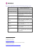
Region Code Frequency Regulations / Max Tx EIRP Operational Band Countries Power Limit Restrictions (see Section 5.4) 96H 12 5.4 GHz ETSI, USA 7dBm 30dBm Radar Avoidance Enabled 13 5.4 GHz Australia, 7dBm 30dBm Radar Avoidance Enabled; Canada Weather Radar Band (5600 to 5650MHz) barred 16 2.5 GHz USA 23dBm >=63dBm 7 Licensed Band operation 19 5.8 GHz India 13dBm 36dBm 5.825MHz to 5.
To address the primary aims the Spectrum Management algorithm implements a radar detection function which looks for impulsive interference on the active channel only. If impulsive interference is detected Spectrum Management will mark the current active channel as having detected radar and initiate a channel hop to an available channel. The previous active channel will remain in the radar detected state for thirty minutes after the last impulsive interference pulse was detected.
5.4.2 RTTT Avoidance and Other Channel Use Restrictions Where regulatory restrictions apply to certain channels these channels are barred. The user should note that the number of channels barred is dependant on the channel raster selected. For example see the effect of the UK RTTT channel restrictions in Figure 16. Barred channels 97H are indicated by a “No Entry” symbol displayed on the “Spectrum Management” web page, see Section 8.3.9 “Spectrum Management Control - With Operational Restrictions”.
5.4.3 Radar Avoidance, i-DFS and Variable (Narrow) Bandwidth Operation PTP 600 Series bridges do not support operation with 5, 10 or 15 MHz channel bandwidth in regions where radar avoidance is enabled. NOTE: Radar avoidance requirements in the 5.4GHz band in the EU is detailed in specification EN 301-893 version 1.3.1 and in the US in the specification FCC part 15.437. Radar avoidance at 5.8GHz is applicable to EU operation and the requirements are currently as defined in EN 301 893 version 1.3.1. 5.
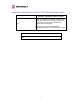
The 2.5 GHz product variant support channel centre frequencies as specified in Table 7. 10H Block Channel Channel Centre Frequencies (MHz) Bandwidth (MHz) 5 Lower 2499.25, 2504.75, 2510.25, 2515.75, 2521.25, 2526.75, 2532.25, 2537.75, 2543.25, 2548.75, 2554.25, 2559.75, 2565.25 Band Segment 10 2502, 2507.5, 2513, 2518.5, 2524, 2529.5, 2535, 2540.5, 2546, 2551.5, 2557, 2562.5 15 2504.75, 2510.25, 2515.75, 2521.25, 2526.75, 2532.25, 2537.75, 2543.25, 2548.75, 2554.25, 2559.
Figure 17 - 2.5 GHz BRS Band Channel Assignments 5.5.2 Power Reduction in the Upper Band Operation in the Upper Band Segment (Table 8 - Power Reduction in the Upper Band) will 103H result in a lower maximum transmit power and the reduction depends on the channel bandwidth.
5.6 5.4GHz Specific Frequency Planning Considerations Adjustment of the lower centre frequency allows the operator to slide the available frequency settings up and down the 5.4 GHz band. See Figure 18 to Figure 21. 104H 105H Figure 18 - 5.4 GHz Available Spectrum Settings - 30 MHz Channel Bandwidth Figure 19 - 5.
Figure 20 - 5.4 GHz Available Spectrum Settings - 10 MHz Channel Bandwidth Figure 21 - 5.
5.6.1 Raster Considerations The PTP 600 Series Bridge 5.4 GHz variant operates on a 10 MHz channel raster (for 30 MHz channel bandwidth) and 6 MHz for the variant channel bandwidths 5, 10 and 15 MHz. The channel raster is set to even centre frequencies. See Figure 18 to Figure 21. 106H 5.6.2 107H Transmit Power Reduction at the Band Edges The 5.4 GHz product variant does not apply any band edge power reduction. 5.7 5.
Figure 23 - 5.8 GHz Available Spectrum Settings - 15 MHz Channel Bandwidth Figure 24 - 5.
Figure 25 - 5.8 GHz Available Spectrum Settings - 5 MHz Channel Bandwidth 5.7.1 Raster Considerations The PTP 600 Series Bridge 5.8 GHz variant operates on a 10 MHz channel raster (for 30 MHz channel bandwidth) and 6 MHz for the variant channel bandwidths 5, 10 and 15 MHz. The channel raster is set to even center frequencies. See Figure 22 to Figure 25. 10H 5.7.2 10H Transmit Power Reduction at the Band Edges Operation at or near the 5.8 GHz band edges can results in a lower maximum transmit power.
The power reduction in the edge channels for 30 MHz is presented in Figure 26. 103H Figure 26 - 5.8 GHz Band Edge TX Power Reduction (Region Code 1 Only) – 30 MHz Channel Bandwidth Operation 5.8 Distance The PTP 600 Series Bridge will operate at ranges from 100 m (330 ft) to 200 km (124 miles), within 3 modes: 0-40km (0-25 miles), 0-100km (0-62 miles) and 0-200km (0-124 miles). Operation of the system will depend on obstacles in the path between the units.
5.9 Networking Information The PTP 600 Series Bridge operates as a transparent Ethernet bridge. Each unit requires an IP address. This IP address is for management purposes only and it plays no part in the operation of the system. IP addresses are assigned during initial configuration as described in Section 7.2 “Installation Procedure”. 106H 5.10 Lightning Protection The amount of lightning protection is dependent on regulatory requirements and the end user requirements.
6 Site Planning 6.1 Site Selection Criteria The following are guidelines for selecting the installation location of the ODU and PDU Plus for a PTP 600 Series Bridge. 6.1.
6.1.3 Path Loss Considerations The path loss is the amount of attenuation the radio signal undergoes between the two ends of the link. The path loss is the sum of the attenuation of the path if there were no obstacles in the way (Free Space Path Loss), the attenuation caused by obstacles (Excess Path Loss) and a margin to allow for possible fading of the radio signal (Fade Margin).
6.1.5 2.5 GHz Product Variant - Receive Sensitivity, Link Loss, Output Power and Threshold Vs Modulation Mode The equipment capability is given in Table 10. This table gives Receive Sensitivity, Link Loss 102H and Output Power for PTP 600 Series Bridge in all modulation modes for channel bandwidth equal to 30 MHz. Adaptive modulation will ensure that the highest throughput that can be achieved instantaneously will be obtained taking account of propagation and interference.
6.1.6 5.4 GHz Product Variant - Receive Sensitivity, Link Loss, Output Power and Threshold Vs Modulation Mode The equipment capability is given in Table 11. This table gives Receive Sensitivity, Link Loss 102H and Output Power for PTP 600 Series Bridge in all modulation modes for channel bandwidth equal to 30 MHz. The values for Receive Sensitivity are typical values in a flat radio channel for an Ethernet frame loss rate of 3E-5.
6.1.7 5.8 GHz Product Variant - Receive Sensitivity, Link Loss, Output Power and Threshold Vs Modulation Mode The equipment capability is given in Table 12. This table gives Receive Sensitivity, Link Loss 1023H and Output Power for PTP 600 Series Bridge in all modulation modes for channel bandwidth equal to 30 MHz. The values for Receive Sensitivity are typical values in a flat radio channel for an Ethernet frame loss rate of 3E-5.
7 Installation Motorola recommends that only qualified personnel undertake the installation of a PTP 600 Series Bridge solution. 7.1 Preparation Before proceeding with the installation you should: 7.2 • Check the contents of all packages against the parts lists shown in the packing list. • Ensure that you have the correct tools for the job. • Ensure that you are qualified to undertake the work. • Ensure that you have taken the correct safety precautions.
7.4 Installation Support Online installation support and contact details for your regional support can be found at http://www.motorola.com/ptp 475H A Frequently Asked Questions (FAQ) section can be found in Section 21. 103H 7.5 Legal Disclaimer IN NO EVENT SHALL MOTOROLA, INC. BE LIABLE FOR ANY INJURY TO ANY PERSONS OR ANY DAMAGE CAUSED DURING THE INSTALLATION OF THE MOTOROLA PTP 600 SERIES PRODUCT. 7.
Pole diameters of 25mm (1”) to 50mm (2”) can be accommodated by inverting the back of the bracket as shown in Figure 27. 103H Figure 27 - Mounting to pole diameters 25mm (1”) to 50mm (2”) When adjustment is complete tighten all bolts to 14Nm (11lb ft). Warning: Do not over tighten the bolts as bracket failure may occur. The enclosure and mounting brackets of the PTP 600 Series Bridge product range are capable of withstanding wind speeds up to 151mph (242kph).
The length of the safety lanyard must not exceed 1m (approx 3 ft) in length. The lanyard should be made from a material that does not degrade in an outdoor environment. The safety lanyard must be fixed to a separate fixing point that is not part of the direct mounting system for the ODU. 7.7 Connecting Up 7.7.1 Preparing The PIDU Plus To ODU Cable NOTE: The maximum cable length between the ODU and the user’s Network Equipment is 100m (330 ft).
Figure 29 - Completed ODU connector Both ends of the ODU cable are terminated in the same way. The above procedure should be repeated for the PIDU Plus end of the cable when the cable routing process is complete. NOTE: The PIDU Plus end of the cable does not employ a cable gland.
7.7.2 Making the Connections at the ODU Looking at the back of the unit with the cable entry at the bottom, the PTP 600 Series Bridge PIDU Plus connection is the first hole on the right (Figure 31) and is labeled “PIDU +”.
7.7.3 Making the PTP 600 Series Bridge PIDU Plus Connection At The ODU The following procedure describes how connection is made at the ODU. It is often easier to carry out this procedure on the ground or a suitable surface prior to mounting the ODU. Ensure that no power is connected to the PIDU Plus or present on the cable before connecting the ODU. Step 1: Assemble the cable as described in Step 2: Insert the RJ45 connector making 5.7.
Should it be necessary to disconnect the PIDU Plus to ODU cable at the ODU, this can be achieved by removing the weather proofing gland and depressing the RJ45 locking tab with a small screwdriver as shown below: Figure 32 - Disconnecting the ODU Warning: Ensure that power is removed from the system at the PIDU Plus to prevent damage to the ODU while making or breaking the connection. 7.7.
7.7.6 Grounding the Installation The Outdoor Unit (ODU) must be properly grounded to protect against power surges. It is the user’s responsibility to install the equipment in accordance with Section 810 of the National Electric Code, ANSI/NFPA No.70-1984 or Section 54 of the Canadian Electrical Code or the National Electrical Code in the country of installation.
Step 3: Replace the cover and secure with the retaining screw 7.7.8 Making the Network Connection at The PIDU Plus – PTP 600 Series Bridge The Network connection is made by connecting the user’s Network Equipment directly to the PIDU Plus LAN port as shown in Figure 33.
7.7.9 Mounting the PTP 600 Series Bridge PIDU Plus This step is optional. Motorola recommends that you mount the PIDU Plus on a wall or other suitable mounting surface. This prevents the unit from being knocked or kicked and can help maintain link availability. Ensure that the reset switch can be accessed when mounting the unit. Step 1: Fix the PIDU Plus to the wall using the lugs provided. Step 2: Make connections as per Section 5.7.
WARNING: The PIDU Plus is not waterproof and should be mounted away from sources of moisture. If mounted outdoors, the unit should be mounted in a rain proof enclosure, preferably ventilated. It is also recommended that you fit a drip loop on the PIDU Plus to ODU cable to ensure that any moisture that runs down the cable into the cabinet or enclosure cannot enter the PIDU Plus. As shown in Figure 34.
WARNING: It is possible for moisture to enter the cable due to damage to the outer protective layer. This moisture can track down the inside of the cable, filling up the drip loop and eventually finding its way into the PIDU Plus. To protect against this the outer protective layer of the cable can be opened up at the bottom of the drip loop to allow this moisture to escape. WARNING: Some network operators employ gel filled cables to get around the problem of moisture ingress and transmission.
7.7.11 Aligning the PTP 600 Series Bridge ODUs The following is a description of the steps taken to establish a radio link between the two units forming the bridge and align the units for the best signal strength. The PTP 600 Series Bridge uses audible tones during installation to assist the installer with alignment. The installer should adjust the alignment of the ODU in both azimuth and elevation 11 until highest pitch tone is achieved .
The following behavior should be noted: • When first started up and from time to time, the Master unit will carry out a band scan to determine which channels are not in use. During this time, between 10 and 15 seconds, the Master unit will not transmit and as a consequence of this neither will the Slave unit.
8 Web Page Reference The web user interface has three main sections. The home page presents to the operator a high level summary of the PTP 600 Series Bridge point-to-point wireless link. The status page presents a more detailed set of system parameters describing the performance of the wireless link together with other key system performance metrics. The final section is the system administration section.
The navigation bar on the left hand side of the web page is used to move between the various management pages. The currently selected page is always highlighted with a dark blue background. The menu is hierarchical. Selecting a menu item which has associated submenu options will automatically display all sub options. A sample web page with the navigation menu is shown in Figure 35 when the ‘Home’ Link is highlighted as the current page.
8.1 Home Page – PTP 600 Series Bridge The home page for the PTP 600 Series Bridge has been designed to display a high level summary of the status of the wireless link and associated equipment. The home page (Figure 1043H 36) normally displays four key system attributes: Wireless Link Status: The Wireless Link Status attribute displays the current status of the PTP 600 Series Bridge wireless link. A state of ‘Up’ on a green background indicates that a point-to-point link is established.
8.1.1 Home Page Alarm Display The home page is also used to display all outstanding major system alarms. Whenever system alarms are asserted, a yellow warning triangle is displayed on web page navigation bar. The warning triangle will be visible from all web pages. Clicking the warning triangle will cause the web page to jump back to the system homepage. Figure 37 shows a sample alarm 1046H screen.
Install Status: If any errors are detected during the installation process, the unit will automatically raise an audible alarm. The install status alarm will be raised with an appropriate reason code, e.g. the alarm will be raised if an incorrect target MAC address is specified for the peer 600 Series Bridge. Ethernet Link Status: If there are any problems with the Ethernet interface, this alarm will be asserted.
Telecoms Channel A Status: Indicates that there is a problem with the telecoms channel A. Possible problems are "No Signal (local)", "No Signal (Remote)", and "No Signal (Local and Remote)". Telecoms Channel B Status: Indicates that there is a problem with the telecoms channel B. Possible problems are "No Signal (local)", "No Signal (Remote)", and "No Signal (Local and Remote)".
8.2 Systems Status Page The status page has been designed to give the system administrator a detailed view of the operation of the 600 Series Bridge from both the wireless and network perspectives. The page is subdivided into three main categories Equipment, Wireless, Telecoms and Ethernet/Internet. The ‘Equipment’ section contains the unit’s inventory and identification information. The ‘Wireless’ section presents the key wireless metrics, which are displayed as a series of measurements and histograms.
The following section details all the attributes displayed on the status page: Link Name: The link name is allocated by the system administrator and is used to identify the equipment on the network. The link name attribute is limited to a maximum size of 63 ASCII characters. Link Location: The link location is allocated by the system administrator and can be used as a generic scratch pad to describe the location of the equipment or any other equipment related notes.
Ethernet Speed and Duplex: The negotiated speed and duplex setting of the Ethernet interface. The speed setting is specified in Mbps. Full Duplex data transmission means that data can be transmitted in both directions on a signal carrier at the same time. For example, on a local area network with a technology that has full duplex transmission; one workstation can be sending data on the line while another workstation is receiving data.
Vector Error: The vector error measurement compares the received signal’s In phase / Quadrature (IQ) modulation characteristics to an ideal signal to determine the composite error vector magnitude. The results are stored in a histogram and expressed in dB and presented as: max, mean, min and latest. The max, min and latest are true instantaneous measurements; the mean is the mean of a set of one second means.
Transmit Data Rate: The data rate in the transmit direction, expressed in Mbps and presented as: max, mean, min, and latest histogram format. The max, min and latest are true instantaneous measurements; the mean is the mean of a set of one second means. See note 14. Expected data rates can be found in Section 4.1.4 “Aggregate Ethernet 1054H 105H 1056H throughput rate v maximum link loss”.
Range: The range 15 14F between the 600 Series bridge ODUs. Refresh Page Period: The Status page refreshes automatically according to the setting entered here (in seconds). This attribute is only displayed when the user is logged on as System Administrator. 8.3 System Administration Pages The following menu options are available for the system administrator and can be password protected. Figure 39 shows the system administration login page. By default a system 106H administrator password is not set.
The features that are only available to the system administrator are: 8.3.
The general configuration allows modification of high level administrative (descriptive) attributes and high level wireless configuration. The LAN configuration sub menu allows the system administrator to modify the Ethernet and IP configuration of the 600 Series Bridge. The telecoms submenu displays the current status of the telecoms interface and allows the configuration of interface loopbacks. The save and restore submenu allows the system administrator to backup and restore the bridge configuration.
While the majority of the system configuration is entered during installation and should never require changing, this page offers the system administrator the ability to change the basic system parameters for both the wireless and Ethernet components. Link Name: User defined identity for the unit (max 63 characters). Link Location: Can be used as a generic scratch pad to describe the location of the equipment.
8.3.1.2 LAN Configuration Page The LAN configuration page (Figure 41) is used by the system administrator to configure the 1064H 600 Series Bridge’s LAN interface. Figure 41 - LAN Configuration Page IP Address: Internet protocol (IP) address. This address is used by the family of Internet protocols to uniquely identify this unit on a network. Subnet Mask: A subnet allows the flow of network traffic between hosts to be segregated based on a network configuration.
VLAN High Priority Traffic Threshold: All packets with an 802.1P priority tag greater than or equal to the indicated value will be treated as a high priority packet for transmission over the wireless link. Use VLAN For Management Interfaces: This controls whether the management interfaces (WWW/SNMP/SMTP/SNTP) use 802.1Q VLAN tags or not. See Section 8.3.1.3. 1065H Ethernet Auto Negotiation This enables the Ethernet configuration to be forced rather than auto negotiated.
All of the above attributes are non-volatile, once set they will be used by the unit even after a power on reboot. A number of attributes, such as IP Address, Subnet Mask and Gateway IP Address and VLAN settings will require a reboot before they are used. If any of these attributes are changed a reboot screen appears asking the user to verify the reboot (Figure 1068H 42 or Figure 43).
8.3.1.3 LAN Configuration Page – Use VLAN For Management Interfaces The layout of the LAN Configuration page changes if this attribute is enabled in order to allow the VLAN VID and VLAN Priority to be set, see Figure 44. The VLAN settings are applied only 107H 107H after the unit is rebooted. Warning: You must ensure that you can access the VLAN which you configure here, otherwise you will be unable to access the unit following the next reboot.
VLAN Management VID: This 802.1Q VLAN VID will be included in packets generated by the management interfaces. Valid settings are in the range 0 to 4094. VLAN Management Priority: This 802.1Q VLAN Priority will be included in packets generated by the management interfaces. Valid settings are in the range 0 to 7. VLAN Management VID Validation: If enabled, the management interfaces will only respond to Ethernet packets tagged with the configured 802.
8.3.1.5 Save and Restore Configuration File The save and restore feature of a PTP 600 Series Bridge allows the system administrator to backup the operation configuration of the wireless unit. It is recommended that this facility is used immediately after a successful PTP 600 Series Bridge installation or prior to any software upgrade. In the unlikely event that a unit has to be replaced in the field, the replacement unit can be reconfigured by simply playing back the saved configuration file.
Figure 47 - Save Configuration File Screen The configuration file is encoded using an ASCII encoding scheme. An example is show in Figure 48.
WARNING: The configuration file is currently restricted to a single software version and can only be restored into a wireless unit operating the software version indicated in the configuration file header. The configuration file can also be used when swapping out a faulty wireless unit. If one of the wireless units is replaced on a wireless link a configuration file captured from the faulty unit can be replaced into the new unit to speed up replacement.
Figure 50 - Reset Configuration and Reboot Confirmation Pop-up On confirmation the PTP 600 Series Bridge will: • Upload the configuration file • Perform data integrity checking • Erase previous configuration • Apply the new configuration • Restart After the unit has restarted the entire configuration from the configuration file will now be active. Note: The IP address of the unit may have also been changed.
8.3.1.6 Telecoms Configuration Page The Telecoms page is only available when the Telecoms Interface has been set to either T1 or E1 in the Installation Wizard. It displays the interface setting and line code for the available telecoms channels. The PTP 600 Series Bridge is able to support two T1 or E1 channels. However, in the “Lite” configuration one of these channels is disabled. The channels are referred to as "Channel A" and "Channel B".
Loopback: Allows the T1 or E1 data stream to be looped back at the copper or wireless interface. During normal operation the loopback must be set to "None". It may be helpful during installation to test the telecoms links by performing loopback connections. A "Copper" loopback connects the received data on a given telecoms interface to the Transmit. A "Copper" loopback may be used, in conjunction with an appropriate test unit, to confirm that the correct connections have been made to the ODU.
8.3.2 Statistics Page The 600 Series bridge statistics page is designed to display some key statistics of the Ethernet Bridge and the underlying wireless performance. Figure 52 - System Statistics Wireless Tx Packets: This displays the total number of good packets the bridge has sent for 19 transmission by the wireless interface . 18F Wireless Rx Packets: This displays the total number of good packets the bridge has received from the wireless interface. See note 19.
Ethernet Tx Packets: This displays the total number of good packets the bridge has sent for transmission by the local Ethernet interface. . See note 19. 108H Ethernet Rx Packets: This displays the total number of good packets the bridge has received from the local Ethernet interface. . See note See note 19. 1082H Packets To Internal Stack: This displays the total number of good packets the bridge has transmitted to the internal stack (e.g., ARP requests, PING requests, HTTP requests). See note 19.
Receive Modulation Mode: The modulation mode currently being used on the receive channel. The number in brackets after the modulation mode and coding rate string is the effective data rate available to all MAC layer protocols. Details on the modulation modes can be found in Section 23.1 “System Specifications”. 1092H Receive Modulation Mode Detail: This supplies the user with information regarding the receive modulation mode in use.
8.3.
The detailed counters page is subdivided into two columns. Column one presents the detailed statistics for the bridge’s Ethernet interface. Column two relates to the wireless interface. The Counters have the following definitions: Tx & Rx Octets: Total number of octets (bytes) transmitted or received over the interface. Rx Drops: Total number of frames dropped due to the lack of sufficient capacity in the receive buffer. Rx Packets: Total number of packets received by the interface.
Tx Multicasts: Total number of good multicast packets. Tx Collisions: Total number frames experiencing collisions. Tx 64 Bytes: Total number 64 byte frames transmitted Tx 65 to 127 Bytes: Total number frames transmitted in the size range 65 to 127 bytes. Tx 128 to 255 Bytes: Total number frames transmitted in the size range 128 to 255 bytes. Tx 256 to 511 Bytes: Total number frames transmitted in the size range 256 to 511 bytes.
Example PTP 600 Series Configuration Data For your convenience these two units have been pre-configured as a link Units: ODU serial number ODU serial number 016780000FFF 016780000FC7 Ethernet MAC address Ethernet MAC address 00:04:56:80:0F:FF 00:04:56:80:0F:C7 Configured as: Master Slave Target MAC address Target MAC address 00:04:56:80:0F:C7 00:04:56:80:0F:FF License Key License Key A471-FE88-428D-E1F3 534F-4F54-D1B0-E2DA IP Address IP Address 169.254.1.2 169.254.1.
8.3.4.1 Manually Configuring The Wireless Units If the installer / system administrator wishes, they may modify the default installation configuration. If only the IP addresses (network configuration) are incorrect it is recommended that the values are changed via the configuration menu (Section 6.3.1.2). If any other 109H parameters require modification then it is recommended that the system administrator use the Installation Wizard.
If a valid license key is not detected in the unit’s non-volatile memory then the user is prompted to enter a valid key. It should be noted that 600 Series bridge units are shipped as link pairs and, as such, valid license keys are entered during the production process. To enter a license key simply type or paste the license key into the data entry box (Figure 54) and click 10H 10H the ‘validate license key’ button. 8.3.4.
Subnet Mask: A subnet allows the flow of network traffic between hosts to be segregated based on a network configuration. By organizing hosts into logical groups, subnetting can improve network security and performance. Gateway IP Address: The IP address of a computer / router on the current network that acts as a gateway. A gateway acts as an entrance / exit to packets from / to other networks. Use VLAN Management Interface: Controls whether the management interfaces (HTTP/SNMP/SMTP/SNTP) use a VLAN.
8.3.4.3 Telecoms Interface If the telecoms interface is configured to either T1 or E1 then the web page will reconfigure itself with the following additional configuration options. Figure 57 - Telecoms Configuration Interface Telecoms Channel Selection: This controls the selection of the telecoms interface standard supported options or T1 and E1. Channel A Line Code: The line code setting of the telecoms interface. This must match the setting of the device connected to this interface.
8.3.4.4 Wireless Configuration Step 2 of the installation wizard requires the installer to enter the wireless configuration parameters. Figure 58 – 5.8 GHz and 5.
Figure 59 - 2.5 GHz Variant - Installation Wizard Wireless Configuration Target MAC Address: It is the MAC Address of the peer unit that will be at the other end of the wireless link. This is used by the system to ensure the unit establishes a wireless link to the correct peer. The MAC Address can be found embedded within the serial number of the unit. The last six characters of the serial number are the last three bytes of the unit’s MAC address.
Link Mode Optimization: Optimizes the link behavior according to the type of traffic that will be bridged. TDD Synchronization Mode: Enables the TDD Synchronization feature (see Section 5.2 for 103H basic description and Section 14 for installation and configuration details). 104H Tx Max Power: This attribute controls the maximum transmit power the unit is permitted to use when installing and executing the wireless link.
Spectrum Management Control: Is used to configure the PTP 600 Series Bridge’s Spectrum Management features, see Section 8.3.7 for more details. i-DFS is the abbreviation 106H for intelligent Dynamic Frequency Selection. This feature continually monitors the spectrum looking for the channel with the lowest level of on channel and co-channel interference. Fixed frequency mode allows the installer to fix transmit and receive frequencies on the units.
Figure 60 – 5.8 GHz and 5.4 GHz Variants - Fixed Frequency Operation Figure 61 - 2.
Installation Tones: Where the use of audio installation tones is not required this control allows the installer to optionally disable the tone generator during the installation process. Once the installer is satisfied with the wireless configuration options then the “Submit Wireless Configuration” button or the “Next” link should be clicked. Figure 62 – 5.8 GHz and 5.
Figure 63 - 2.5 GHz Variant - Installation Wizard Confirm Configuration If the settings are correct and appropriate, click the “Confirm Configuration, Arm Installation and Reboot” button. The user will now be prompted to confirm the action (Figure 64).
All the attributes are committed to non-volatile memory. Immediately following the write to non-volatile memory the unit is reset. Note: If you have changed the Ethernet parameters you must reconnect using the correct network and address settings. 8.3.4.5 Disarm Step 5 of the installation wizard is the disarm phase. Figure 65 – 5.8 GHz and 5.
Figure 66 - 2.5 GHz Variant - Disarm Installation Once Section 8.3.4.4 is complete pressing the “Disarm Installation Agent” button completes 15H the installation process 20F 21 and the audible installation tone will be switched off. If the installer wishes to modify the installation configuration then the ‘Back’ link can be used to access the installation wizard steps described above. 21 The installation process is completed when both ends of the link are ‘disarmed’.
After disarming the wireless link the user is presented with one of two possible configuration pages, see Figure 67 and Figure 68. The screen presents hyperlinks to the main 16H 17H configuration and spectrum management pages. Figure 67 - Optional Post Disarm Configuration 1 Figure 68 - Optional Post Disarm Configuration 2 After installation the system administrator may wish to modify the wireless units descriptive configuration (link name and link location).
The design of the installation screen has been deliberately kept simple and uncluttered. An example of the installation screen is shown in Figure 69. Both the PDA and the large format 18H installation screen have the same content and only differ in size. The PDA installation screen is 232 by 220 pixels to be compatible with the typical size of a PDA screen. Figure 69 – Graphical Installation Screen The screen displays the receive power over the last three minutes.
8.3.6 Software Upgrade The 600 Series system has two software image banks; one is a fixed image which is stored in protected non-volatile memory and cannot be modified by the user. The second bank is used by the system administrator to upgrade the firmware when necessary. Figure 70 shows the 19H 120H main software upgrade web page.
The software image will now be uploaded to the unit. This upload should only take a few seconds. Once complete the image is verified and validated to ensure that no errors occurred during transfer and that the image is valid to run on the current platform. If there are any problems a warning screen will appear. The unit being upgraded will now display information about the build it currently has stored in the image bank and the one that’s just been uploaded.
During the write process the progress of the upgrade is displayed on the progress tracking page (Figure 72). The upgrade process should not be interrupted. Interruption of this process 124H can result in a corrupt main software image, which will result in the recovery image been booted at the next reset cycle.
Reboot the unit by clicking the “Reboot Wireless Unit” button. You will be asked to confirm this action as shown in Figure 74.
This will reboot the unit, taking up to 120 seconds. During this time you will not be able to communicate with the unit. If you cannot communicate with the unit after 120 seconds, this could indicate a problem with the memory update process. Under these circumstances the user should enter “Recovery Mode”, see Section 9. 127H After the reboot the user should check that the required software image is loaded and running. NOTE: Please ensure that you are upgrading the correct units.
8.3.7.2 Spectrum Management Measurements The 600 Series Bridge performs two mean signal measurements per TDD cycle, per channel. This mean measurement represents the mean received signal power for the 40 μS measurement period. The Spectrum Management algorithm collects measurements equally from all channels. This process is called the Channel Availability Check (hereafter referred to by the acronym CAC).
Mean of Means is the arithmetic mean 22 21F of the measured means during a quantization period. The mean of means is a coarse measure of signal interference and gives an indication of the average interference level measured during the quantization period. The metric is not very good at predicting intermittent interference and is included to show the spread between the mean of means, the 99.9% percentile and the peak of means. Important Note: Spectrum Management uses the 99.
Figure 75 - Spectrum Management as seen from the Master Figure 76 - Spectrum Management as seen from the Slave 137
Figure 75 shows an example Spectrum Management webpage as seen from the master. 13H Figure 76 shows an example Spectrum Management webpage as seen from the slave. It 132H should be noted that the key configuration attributes are not available on the slave web page. 8.3.7.5 Spectrum Management Configuration The following section describes the user modifiable configuration accessible from the Spectrum Management webpage. It is recommended that the default values are maintained.
Channel Bandwidth (not configurable): shows the value of the variable channel bandwidth selected. 8.3.7.6 Barring Channels Channels can only be barred / unbarred by the system administrator from the master Spectrum Management web page. The barring / unbarring operations are disabled on the slave web page. If an attempt to bar / unbar a channel is made at the slave, a warning dialog is generated.
The active channel (channel 5 in Figure 77) is always marked using hatched green and white 13H lines. The width of the hatching is directly proportional the 30 MHz spectral occupancy of the channel. The individual channel metrics are displayed using a colored bar and an ‘I’ bar.
8.3.7.8 Active Channel History The active channel history is a time series display of the channels used by the PTP 600 Series Bridge over the last 25 hours. The active channel history is activated from the main Spectrum Management page using the ‘Active Channel History’ hyperlink. An example of the active channel history display is shown in Figure 78. Where there are parallel entries on the 134H display this signifies that the wireless link occupied this channel during the measurement period.
Figure 79 shows an example time series plot. A time series plot displays the previous 132 135H measurement quantization periods. If the PTP 600 Series Bridge has not been running for 132 quantization periods then only the number of measurement quantization periods that are available are displayed. GREEN Peak of Means interference measurement BLACK 99.
8.3.8 Spectrum Management (Fixed Frequency and WIMAX) The PTP 600 Series Bridge software allows a user to optionally fix transmit and receive frequencies for a wireless link. Once configured, the spectrum management software will not attempt to move the wireless link to a channel with lower co and adjacent channel interference. Therefore this mode of operation is only recommended for deployments where the installer has a good understanding the prevailing interference environment. (See Section 8.3.4.4).
Channel barring is disabled in fixed frequency mode; it is not required as dynamic channel hopping is prohibited in this mode. The only controls available to the master are the Statistics Window and Interference Threshold attributes. They will have no effect on the operation of the wireless link and will only effect the generation of the channel spectrum graphics. The active channel history menu is removed in this mode of operation as channel hopping is prohibited.
• The only controls available to the master are the Interference Threshold attribute. This has no effect on the operation of the wireless link and will only affect the generation of the channel spectrum graphics. See Figure 82. 140H • Extra color coding of the interference histogram is provided. See Table 17.
Figure 83 - Spectrum Management Slave Screen With Operational Restrictions The colored bar represents the following channel state: Green Active The channel is currently in use hosting the Point-to-Point wireless link Orange Interference The channel has interference above the interference threshold Blue Available The channel has an interference level below the interference threshold and is considered by the Spectrum Management algorithm suitable for hosting the Point-to-Point link Grey Barred The
8.3.10 Spectrum Management – Example of 2.5 GHz Product variant As described in Section 52, the 2.5 GHz product variant can operate in three frequency 14H bands. Figure 84 shows an example of a Lower Band with a 30 MHz channel bandwidth. 145H Figure 84 - 2.
8.3.11 Remote Management Page The Remote Management page (Figure 85) allows the system administrator to configure the 146H remote management of the PTP 600 Series Bridge.
8.3.11.1 SNMP (Simple Network Management Protocol) The industry standard remote management technique is SNMP (Simple Network Management Protocol). The PTP 600 Series Bridge supports version 1 and version 2c of the SNMP protocol. 8.3.11.2 Supported Management Information Bases (MIBS) The PTP 600 Series Bridge SNMP stack currently supports three distinct MIBs: • MIB-II, RFC-1213, The PTP 600 Series Bridge supports the ‘System Group’ and ‘Interfaces Group’.
8.3.11.3 Diagnostics Alarms A number of diagnostics alarms have been added to allow SNMP agents to receive traps and emails if required. Checking the control “Enabled Diagnostic Alarms” in SNMP and/or SNTP selects all the alarms shown in Figure 86. Users can access the sub-menu “Diagnostic 147H Alarms” to modify the alarms selected.
8.3.11.4 SNMP Configuration SNMP State: The SNMP state attribute controls the creation of the SNMP features. Changing the SNMP state attribute requires a mandatory reboot of the unit. Only when the SNMP state is enabled at system start-up will the SNMP processor task be created. SNMP Enabled Traps: The SNMP Enabled Traps attribute controls which SNMP Traps the unit will send.
SMTP Port Number: The SMTP Port Number is the port number used by the networked SMTP server. By convention the default value for the port number is 25. SMTP Source Email Address: The email address used by the 600 Series bridge to log into the SMTP server with. This must be a valid email address that will be accepted by your SMTP Server SMTP Destination Email Address: The email address to which the 600 Series bridge will send the alert messages. 8.3.11.
Set Date: Displays the current date. The year, month and day can be set using the dropdown selection boxes. Time Zone: See Section 8.3.11.7. 149H Daylight Saving: See Section 8.3.11.7. 150H 8.3.12 Diagnostics To further enhance the diagnostic capabilities of the PTP 600 Series, the storage of link performance histograms has been extended to 31. To optimize RAM (volatile memory) usage a cascading histogram approach has been adopted.
8.3.12.1 Diagnostic Plotter New for the PTP 600 Series is the system administration diagnostic plotter facility see Figure 15H 87. Figure 87 - Diagnostic Plotter The diagnostic plotter allows the system administrator to view the cascading histogram data in an easily accessible graphical form. The plot always displays three traces, maximum, minimum and mean by default. The diagnostic selector allows the user to select the various categories of histogram.
The trace selection allows the user to control which traces are plotted. As with other management pages the page refresh period can be used to interactively monitor the wireless link. 8.3.12.2 Diagnostics Download The diagnostics Download page allows the system administrator to download snapshots of system diagnostics.
8.3.13 Change System Administration Password This page (Figure 89) is used to change the password for the system administration (The 152H factory default is blank). Figure 89 - Password Change To change the password any combination of alphanumeric characters, up to 31 characters in length, can be used. 8.3.14 License Key The License Key data entry page allows the system administrator to update the 600 Series bridge license key. Figure 90 shows a sample license key data entry page.
The user must enter the license key and click the ‘Validate License Key’ button to check that the key is valid and program it to non-volatile memory. If a valid license key is detected then the user will be presented by a system reboot screen. Figure 91: License Key reboot Screen The user will then be asked to confirm the reboot (Figure 92).
8.3.15 Properties The web page properties screen allows the user to configure the web page interface. Figure 93 – Properties WEB Properties: Disable Front Page Login Allows access to homepage and status page web pages without forcing a login as the system administrator. WEB Properties: Disable HP NO-CACHE META data: Removes the HTTP NO-CACHE META clause from all dynamically created web pages.
8.3.16 Reboot The reboot page allows the system administrator to perform commanded reboots of the wireless unit. The reboot page also allows the system administrator to view a list of past reboot reasons. The “Previous Reasons For Reset/Reboot” field has been implemented as a drop down selection box, where the latest reason for reboot is located at the top of the list.
9 Recovery Mode The Motorola PTP 600 point-to-point wireless Ethernet bridges have a special mode of operation that allows the user to recover a unit from configuration errors or software image corruption. Recovery mode is entered by depressing the Recovery Switch located on the underside of the PIDU Plus while applying mains power, as shown in Section 3.3.2. The Recovery Switch 15H should be held in the depressed state for between 10 and 20 seconds after the application of mains power.
Clicking on the warning page image will take the user on to the Recovery Option Page (Figure 97). 157H Figure 97 - Recovery Options Page The recovery options available are: Upgrade Software Image: This allows the user to reload a software image. This may be the original image if software corruption is suspected or a step back to an old image if an incorrect image has just been loaded.
Software Version: This is the software version of the recovery operating system permanently installed during manufacture. Recovery Reason: Indicates the reason the unit is operating in Recovery mode. Possible reasons are “Recovery button active” or “Invalid or corrupt image” MAC Address: The MAC address shown here is the MAC address of the unit programmed during manufacture. 9.
After carefully checking that correct image has been downloaded the user should reboot the unit by pressing the “Reboot Wireless Unit” button. The user will then be presented with a pop up box asking them to confirm the action (Figure 100) 16H Figure 100 - Reboot Confirmation Pop Up The unit will now reboot. Providing the unit configuration is still intact the unit should restart in normal operational mode and the link should recover.
9.2 Reset IP & Ethernet Configuration To reset IP & Ethernet configuration back to factory defaults the user should press the “Reset IP & Ethernet Configuration back to factory defaults” button on the “Recovery Options” page (Figure 97). The user will now be presented with a pop up box asking them to confirm the 163H4 action (Figure 101). 165H Figure 101 - Confirm Reset to Factory Default Pop Up On confirmation the following page will be displayed (Figure 102).
The user will now be presented with a pop up box asking them to confirm the action (Figure 167H 103) Figure 103 - Reboot Confirmation Pop Up The unit will now reboot. The unit should now start up in normal mode but with the IP address set to 169.254.1.1 and the Ethernet interface set to auto-negotiate and auto-MDI/MDIX. Should the unit fail to start up the user should refer to Section 10. 168H 9.
On confirmation the following page will be displayed (Figure 105). The user should now 17H reboot the unit by pressing the “Reboot” button.
The user will now be presented with a pop up box asking them to confirm the action (Figure 172H 106) Figure 106 – Erase Configuration - Reboot Confirmation Pop Up The unit will now reboot. The unit should now start up in normal mode but with all configuration erased. Should the unit fail to start up the user should refer to Section 10.
9.4 Reboot To erase the unit’s configuration the user should press the “Reboot” button on the “Recovery Options” page (Figure 97). The user will now be presented with a pop up box asking them to 174H confirm the action (Figure 107). 175H Figure 107 – Recovery - Reboot Confirmation Pop Up The unit will now reboot. The unit should now start up in normal operational mode. Should the unit fail to start up the user should refer to Section 10.
10 Fault Finding If communication has been lost with the unit at the near end of the link then there may be a hardware fault with the wiring, network or hardware. Go to the hardware section below. If communication with the far end of the link is lost then go to the radio section below. 10.1 Hardware If there are problems suspected with the link hardware the following procedure is recommended. The following diagram illustrates the main system connections: Figure 108 - Main System Connections 10.1.
If it does illuminate then either the ODU is drawing too much current, or the power wiring to the ODU is short circuit or the PSU is supplying insufficient power. The likely fault can be determined by removing the jumper (J906), found inside the removable cover of the PIDU Plus, and measuring the current taken with an ammeter placed across the 2 jumper pins. This is normally 10mA without the ODU connected and 300mA to 1A when the ODU is connected.
Power Indoor Unit LED check chart: Mode Green LED Yellow LED No Ethernet Cable Connected Yellow LED Ethernet Cable Connected between PIDU Plus and NIC/Switch/Hub No Power Applied Off Off Off Will flash once per second regularly approximately 30 seconds after power applied for 10 seconds then operate as Ethernet Link/Activity LED Power Applied On Will flash once per second regularly approximately 30 seconds after power applied for 10 seconds then will go out and stay out Valid Ethernet Link and n
5. Ensure that there is greater than 100K ohms between pin 1 and ODU ground for all cable lengths. 6. Ensure that there is greater than 100K ohms between pin 8 and ODU ground for all cable lengths CAT-5 Length (Meters) Resistance between pins 1 & 2, 3 & 6 , 4 & 5 and pins 7 & 8 (ohms) Resistance between pins 1&3 (ohms) Resistance between pins 4&7 (ohms) 0 0.8 1.0 1.6 10 2.5 2.7 3.3 20 4.2 4.4 5.0 30 5.9 6.1 6.7 40 7.6 7.8 8.4 50 9.3 9.5 10.1 60 11.0 11.2 11.8 70 12.7 12.
• Check License key • Check Master Slave • Check that the link has not been further obscured or the ODU misaligned. • Check the DFS page at each end of the link and establish that there is a quiet wireless channel to use. If there are no faults found in the configuration and there is absolutely no wireless signal retry the installation procedure. If this doesn’t work then the ODU may be faulty. 10.2.
11 Lightning Protection EMD (Lightning) damage is not covered under warranty The recommendations in this user manual when installed correctly give the user the best protection from the harmful effects of EMD However 100% protection is neither implied nor possible 11.1 Overview The idea of lightning protection is to protect structures, equipment and people against lightning by conducting the lightning current to ground via a separate preferential solid path and by reducing the electromagnetic field.
The following diagrams (Figure 109 & Figure 110) show this zoning pictorially: 180H 18H Equipment mounted in Zone A should be capable of carrying the full lightning current. Mounting of the ODU in Zone A is not recommended. Mounting in Zone A should only be carried out observing the rules governing installations in Zone A 24F 25 Failure to do so may put structures, equipment and life at risk. Equipment mounted in Zone B should be grounded using grounding wire of at least 10 AWG.
Figure 109 - ODU mounted in Zones A & B Figure 110 - Showing how the use of a Finial enables the ODU to be mounted inside Zone B 176
Zone A Zone B Earth ODU Mandatory Mandatory Screen Cable Mandatory Mandatory Surge Arrestor Unit at ODU – ALPUORT Mandatory Mandatory Earth Cable at Building Entry Mandatory Mandatory Surge Arrestor Unit at Building Entry – ALPU-ORT Mandatory Mandatory Table 19 - Protection Requirements Figure 111 - Diagrammatically showing typical wall and mast installations 177
A typical installation is shown in Figure 112 and Figure 113. 182H 183H Note: Grounding Points are shown unprotected for clarity. Grounding points should be adequately weatherproofed to prevent corrosion and possible loss of ground continuity.
Figure 113 - Lower Grounding Configuration An Andrew Grounding Kit and Surge Arrestor Unit must be located at the ODU and reliably grounded as shown in Figure 95. There may also be a regulatory requirement to crossbond the screened CAT-5 at regular intervals up the mast. Refer to local regulatory requirements for further details.
A second Surge Arrestor Unit should be mounted at the building entry point and must be grounded. The termination of the CAT-5 Cable into the Surge Arrestor Unit is illustrated in Table, Table 184H 21 and Figure 114. The screen from the cable must be terminated into the ground terminal 185H within the unit to ensure the continuity of the screen. Earth Sleeving should be used to cover the shield ground connection to prevent internal shorting within the unit.
Figure 114 - Surge Arrestor ALPU-ORT Connection Illustration Note: Cable screens have been sleeved.
11.3 Testing Your Installation If you have followed the above instructions you will have wired your system to the following diagram: Figure 115 - Simplified Circuit Diagram (Only One Transtector Shown For Clarity) 11.3.1 Pre-Power Testing Before plugging in the RJ45 to the PIDU check the impedances at the RJ45 as described in 10.1.3. 186H 11.3.2 Post-Power Testing The Correct Operation is as follows 1. Connect the RJ45 to the PIDU and apply power to the PIDU, the power LED should illuminate continuously.
The Ethernet LED flashes ten times but irregularly Irregularly flashing, seen as a short gap followed by a long gap, indicates that the ODU has booted in recovery mode. This may be due to either the installation wiring or a corrupted main code image in the ODU. The Ethernet LED flashes ten times but does not show Ethernet activity Failure of the Ethernet LED to show Ethernet activity can be due to wiring to pins 1&2 and 3&6 being incorrect, for example if the wiring to pins 1 and 3 are crossed.
12 Wind Loading 12.1 General Antennas and electronic equipment mounted on towers or pole mounted on buildings will subject the mounting structure to lateral forces when there is appreciable wind. Antennas are normally specified by the amount of force (in pounds) for specific wind strengths. The magnitude of the force depends on both the wind strength and size of the antenna. 12.
Lateral Force (kg) at wind speed (m/s) Largest Surface Area (sq m) 30 40 50 60 70 PTP 600 Series Bridge - Integrated 0.130 12 22 34 49 66 PTP 600 Series Bridge Connectorized 0.093 9 16 24 35 48 Table 23 - Lateral Force – Metric Note: When the connectorized version of 600 Series bridge is used with external antennas, the figures from the antenna manufacturer for lateral force should be included to calculate to total loading on the mounting structure. 12.
Chicago, Illinois 87 Hatteras, North Carolina 110 Miami, Florida 132 New York, New York 99 Pensacola, Florida 114 UK Meteorological Office, www.meto.gov.uk 483H Peak wind speed contour maps can be found as Fig 3a/3b at: http://www.meto.gov.uk/education/historic/1987.
13 PTP 600 Series Bridge – Connectorized Model 13.1 Scope This section details the changes and additional features relevant to the connectorized version of the PTP 600 Series systems, OS 58C. 13.2 Product Description 13.2.1 Hardware The Connectorized PTP 600 Series Bridge is a variant designed to provide the system integrator and installer with the ability to provide extra capability to cope with very difficult radio links compared to the PTP 600 Series Integrated model.
13.2.2 Antenna Choices – 5.8 GHz The integrated antenna has a gain of 23 dBi. In non-FCC regions antenna choice is not restricted but any region specific EIRP limit should be obeyed, see Table 6 in Section 5.3 “Region Codes” 189H 190H In FCC regions external antennas from the list in Section 13.7 “Antennas for USA / Canada” 19H 192H can be used with the Connectorized version of the 600 Series Bridge.
13.3 Software/Features The variant operates in the same way as the basic 600 Series bridge and is released initially with the feature set of the Connectorized 600 Series bridge. The areas where the functionality is modified are: 13.3.1 Status Page The link loss calculation presented on the Status Page of the management interface has to be modified to allow for the increased antenna gains at each end of the link.
13.3.2 Configuration Pages The amended Configuration web page is shown below as Figure 118.
13.3.3 Installation Pages The installer is prompted to enter the Antenna Gain and Cable Loss (Connectorized PTP 600 Series Bridge to antenna) at each end of the link. The Installation Page(s) is shown as Figure 194H 119 to Figure 121. 195H Figure 119 - Connectorized PTP 600 Series Bridge ‘Installation Wizard’ Page Antenna Gain: Gain of the antenna you are connecting to the unit, see Table 25. 196H Cable Loss: Loss in the cable between the ODU and the antenna.
Spectrum Management Control: Is used to configure the 600 Series Bridge Spectrum Management features, see Section 8.3.7 for more details. iDFS is the 197H abbreviation for intelligent Dynamic Frequency Selection, which continually monitors the 5.8 GHz spectrum looking for the channel with the lowest level of on channel and co-channel interference. Fixed frequency mode allows the installer to fix the Transmit and receive frequencies on the units.
EIRP The Confirm Installation Page displays the EIRP (Effective Isotropic Radiated Power), which describes the strength of the radio signal leaving the wireless unit. This allows the operator to verify that their link configuration (Max Transmit Power, Antenna Gain and Cable Loss) do not cause the link to exceed any applicable regulatory limit.
13.4 Deployment Considerations The majority of radio links can be successfully deployed with the 600 Series bridge. It should only be necessary to use external antennas where the Link Budget Calculator indicates marginal performance for a specific link – for example when the link is heavily obscured by dense woodland on an NLOS link or extremely long LOS links (>80km or > 50 miles) over water.
13.6.2 Cable Losses (FCC Regions Only) The FCC approval for the product is based on tests with a cable loss between the units of approximately 1.2dB at 5.8GHz. The use of lower cable losses would result in the installation being outside the FCC rules. As an indication, 1.2dB of cable loss corresponds to the following cable lengths excluding connector losses (source: Times Microwave). Length for 1.2dB Cable Loss at 5.8GHz Cable (ft) (m) LMR100 1.9 0.6 LMR200 4.6 1.4 LMR300 7.25 2.2 LMR400 11.
Manufacturer Antenna Type Gain (dBi) 33.4 Flat Plate Paraboli c Dish Y Andrew Andrew 3-foot Parabolic, P3F-52 (33.4dBi) Andrew Andrew 3-foot Dual-Pol Parabolic, PX3F-52 (33.4dBi) 33.4 Y Andrew Andrew 4-foot Parabolic, P4F-52 (34.9dBi) 34.9 Y Andrew Andrew 4-foot Dual-Pol Parabolic, PX4F-52 (34.9dBi) 34.9 Y Andrew Andrew 6-foot Parabolic, P6F-52 (37.6dBi) 37.6 Y Andrew Andrew 6-foot Dual-Pol Parabolic, PX6F-52 (37.6dBi) 37.
Manufacturer Antenna Type Gain (dBi) 29 Flat Plate Paraboli c Dish Y RadioWaves Radio Waves 2-foot Parabolic, SP2-5.2 (29.0dBi) RadioWaves Radio Waves 3-foot Dual-Pol Parabolic, SPD35.2 (31.1dBi) 31.1 Y RadioWaves Radio Waves 3-foot Parabolic, SP3-5.2 (31.4dBi) 31.4 Y RadioWaves Radio Waves 4-foot Dual-Pol Parabolic, SPD45.2 (34.4dBi) 34.4 Y RadioWaves Radio Waves 4-foot Parabolic, SP4-5.2 (34.8dBi) 34.8 Y RadioWaves Radio Waves 6-foot Dual-Pol Parabolic, SPD65.2 (37.5dBi) 37.
13.8 Installation The section covers the generic installation instructions for the Connectorized versions of the PTP 600 Series point-to-point wireless Ethernet bridges. The actual installation procedure will depend on antenna choice, cable choice, required antenna separation etc. 13.8.1 Antenna Choice Table 25 shows a wide variety of antennas that can be used with the Connectorized 600 120H Series bridge. The main selection criteria will be the required antenna gain.
13.8.4 Miscellaneous supplies The following miscellaneous supplies will be required: • Cable ties, cable cleats – for securing cables • Self-amalgamating tape – to weatherproof the RF connectors • PVC tape – for additional protection of the RF connectors and securing cables 13.8.5 Mounting the Connectorized 600 Series Bridge A Connectorized 600 Series bridge is shipped with the same bracket as supplied with an Integrated unit. Details on the use of this bracket can be found in Section 3.3.7.
13.8.7 Alignment Process When aligning antennas deployed with a Connectorized 600 Series bridge unit it may not be possible to hear the alignment tone emanating from the unit. In this case it may be necessary for a second installer to assist in the operation. Alternatively, it may be possible to extend the tube on the supplied stethoscope to give a longer reach.
13.8.10 Completing the Installation The installation should be completed by checking all mounting nuts bolts and screws, securing all cables and weatherproofing the installation. Warning: Finally tightening the antenna mountings may cause the antenna alignment to be altered, due to distortion in the mounting bracket caused by action of tightening.
All joints should be weatherproofed using self-amalgamating tape. It is recommended that a layer of PVC tape be placed over the self-amalgamating tape to protect the joint while the self-amalgamating tape cures and gives additional protection. Figure 123 shows this 1209H diagrammatically for the 600 Series bridge end of the antenna cables. If the antenna manufacturer has not supplied guidance on this matter, the same technique should be employed at the antenna end of the cable.
13.9 Additional Lightning Protection The following guidelines should be applied in addition to those described in Section 11 120H ”Lightning Protection”. 12H 13.9.1 ODU Mounted Outdoors Where the ODU is mounted outdoors and is mounted some distance from the antenna, it is advisable to add additional grounding by utilizing Andrew Assemblies (such as Andrew Type 223158 www.andrew.com) as shown in Figure 124.
13.9.2 ODU Mounted Indoors Where the ODU is mounted indoors, lightning arrestors should be deployed where the antenna cables enter the building as shown in Figure 125. 123H Figure 125 - Lightning Arrestor Mounting The lighting arrestors should be ground bonded to the building ground at the point of entry. Motorola recommends Polyphaser LSXL-ME or LSXL lighting arrestors. These should be assembled as show in Error! Reference source not found..
14 TDD Synchronization Configuration and Installation Guide 14.1 Introduction This Section gives instructions for installing and configuring the TDD (Time Division Duplex) Synchronization feature for Motorola PTP600 Series bridges. Using this feature, a single frequency channel is assigned to both the transmitter and the receiver. This has many advantages such as: • Minimising interference between multiple links on a single mast.
14.2 TDD Synchronization Installation and Wiring Guidelines As mentioned in Section 5.2.4, enabling the TDD Synchronization 124H 25F 26 feature is a two-stage process: 1. Install GPS Synchronization unit 2. Use web interface to enable and configure parameters 14.2.
Figure 127 - GPS Synchronization Unit NOTE: Refer to GPS Sync Box User manual for al the details on the lengths of all the cables used to connect the GPS Sync Box to the ODU. Figure 128 shows the connections in the GPS Sync Box unit and Figure 129 is a diagram that 127H 128H shows how to connect the GPS Sync box to the ODU and the Lightning protection unit.
Figure 129 - TDD Sync - PTP600 Deployment Diagram NOTE: Installation details of the GPS Sync Box are described in the GPS Sync Box User Manual. Figure 130 shows an example of mast installation using lightning protection and a GPS Sync 129H Box unit.
14.3 Configuring the TDD Synchronization Feature TDD synchronization is enabled and configured using the install wizard during the installation 27 process of the link . 26F 14.3.1 TDD Synchronization Enable There are two synchronization modes (see Figure 131): 120H 1. Disabled (Default): PTP600 operates exactly as for existing system releases (no TDD Synchronization) 2. Enabled: PTP600 TDD Synchronization is enabled.
When TDD Synchronization is enabled, note the following changes to the existing controls in the Installation wizard screens: ¾ ‘Ranging Mode’ and ‘Target Range’ controls are disabled on the wireless configuration page. ¾ ‘Spectrum Management’ Control is forced to ‘Fixed Frequency’ operation only. 14.3.2 TDD Synchronization Configuration Menu When TDD Synchronization is enabled, there is an extra installation screen (“TDD Synchronization”) as shown in Figure 132.
Longest Link in Network: Default value is 100 kms (60 miles). It is the distance of the longest link in the network (maximum is 200 kms or 120 miles). Bandwidths in Network: It is very likely that there will be several different channel bandwidths in a given network. Table 26 gives a list of bandwidth combinations that permit 124H synchronization without gross loss of efficiency. Note that depending on the channel bandwidth size, only subsets of Table 26 will be shown in the configuration wizard screen.
Colocated Masters: choose “Yes” to indicate that ODUs are colocated on the same mast. If the option “No” is selected, then the control below is displayed (see Figure 133): 126H Master to Master Range: Maximum range is 200 Kms (120 miles). Slave Interfere: Select “Yes” to indicate that a Slave ODU interferes. If the option “No” is selected, then the control below is displayed (see Figure 133 ): 127H Slave to Slave Range: Maximum range is 200 Kms (120 miles).
Configure Link Range: Choose “yes” to enter the range of the link in control below: Note that Link Range MUST be less or equal to “Longest Link in Network”. TDD Holdover Mode: Two values: “Strict” and “Best Effort”. If a PTP 600 master ODU is configured for a TDD Holdover Mode set to “Strict”, then it will not transmit when synchronization is lost.
14.3.2.1 TDD Synchronization Configuration – Expert Mode When “Expert Mode” is selected, the user is required to configure the parameters 28 27F shown in Figure 134. 128H Figure 134 - Configure TDD Synchronization Expert Mode The configuration parameters are described below.
TDD Frame Duration: the available frame rates are given in Table 27.
Maximum Burst Duration: When operated in TDD Synchronization mode, the PTP 600 ODU will support the combinations of channel bandwidth and OFDM size as listed in Table 1230H 28. Note that in IP Mode, select the largest supported value for the appropriate bandwidth combination to maximize throughput. In TDM mode, select an appropriate value to achieve the lowest latency consistent with the most robust modulation mode.
NOTE: In TDM link optimization mode, burst duration should be selected so as to achieve the lowest latency consistent with throughput sufficient to support the maximum allowed configuration of internal TDM interfaces at the most robust modulation mode. Table 29 lists 123H the frame duration thresholds for TDM operation. Frame duration depends on burst duration.
14.3.2.
Figure 136 - Disarm Following TDD Synchronization 219
15 E1/T1 Installation Guide 15.1 Preparing the PTP 600 Series Bridge E1/T1 Cable Note: The maximum cable length between the ODU and the customers terminating equipment is 200m (656 feet) for T1. The E1/T1 cable should be assembled to the following instructions: Step 1: Assemble gland on cable as shown Step 2: Strip the outer insulation Step 3: Arrange conductors as shown in fig.
This procedure applies to the ODU termination. The above procedure should be repeated for the customer equipment end of the cable when the cable is terminated with a RJ45. Figure 138 - RJ45 Pin Connection (T568B Color Coding) 15.2 Making the Connection at the ODU Looking at the back of the unit with the cable entry at the bottom, the PTP 600 Series Bridge E1/T1 connection is the first hole on the left (Figure 139) and is labeled E1/T1.
The following procedure describes how connection is made at the ODU. It is often easier to carry out this procedure on the ground or a suitable surface prior to mounting the ODU. Ensure no power is connected to the PIDU Plus.
Should it be necessary to disconnect the E1/T1 cable at the ODU this can be achieved by removing the weatherproofing gland and depressing the RJ45 locking tab with a small screwdriver as shown in the opposite photograph.
15.3 Routing the Cable After connecting the cable to the ODU it can be routed and secured using standard cable routing and securing techniques. When the cable is in place it can then be cut to the desired length. 15.4 Fitting a Surge Arrestor If you have opted to fit a Surge Arrestor, it should be installed as described in Section A1.5 “Lightning Protection” 15.
Figure 142 - Diagrammatically Showing the E1-T1 Connections 225
Figure 143 - Two E1-T1-120 Ohms signal Balanced to PTP600 Interface 226
16 Lightning Protection 16.1 Overview Section 11 in the main body of this manual contains the requirements for the Motorola PTP 1234H 600 Series deployment. This section details the additional requirements for the deployment of E1/T1. 16.2 Recommended Additional Components for E1/T1 Installation.
Figure 144 - Typical Mast Installation with the addition of the E1-T1 cable 228
Note: There may be a local regulatory requirement to cross bond the CAT 5 drop cable at regular intervals to the mast. This may be as frequent as every 10 meters (33 feet).
16.3 Surge Arrestor Wiring An Andrew Grounding Kit and Surge Arrestor Unit must be located at the ODU and reliably grounded as shown in Figure 111. There may also be a regulatory requirement to crossbond 1237H the screened CAT-5 at regular intervals up the mast. Refer to local regulatory requirements for further details. A second Surge Arrestor Unit should be mounted at the building entry point and must be grounded.
Figure 146 - Surge Arrestor ALPU-ORT Connection Illustration 231
16.4 Testing Your Installation If you have followed the above instructions you will have wired your systems to the following diagram: Figure 147 - Simplified Circuit Diagram (Only One Transtector Shown For Clarity) 16.4.1 Pre-Power Testing Before connecting your E1/T1 source, check the following resistances: 1. Check the cable resistance between pins 3 & 6 (Green/White & Green) and 7 & 8 (Brown/White & Brown). Check against Table 33 column 2. 124H 2.
CAT-5 Length (Meters) Resistance between pins 3 & 6 and pins 7 & 8 (ohms) Resistance between pins 1 & 2 and pins 4 & 5 (ohms) 0 0.8 1.3 10 2.5 3.0 20 4.2 4.7 30 5.9 6.4 40 7.6 8.2 50 9.3 9.8 60 11.0 11.5 70 12.7 13.2 80 14.4 14.9 90 16.1 18.2 100 17.8 18.
17 Data Rate Calculations To aid the calculation of data rate throughput, the following plots of throughput verses link range have been produced for all the PTP 600 Series modulation modes, assuming the units are connected using Gigabit Ethernet.
Figure 149 - QPSK 0.63 Single Payload Figure 150 - QPSK 0.
Figure 151 - 16 QAM 0.63 Single Payload Figure 152 - 16 QAM 0.
Figure 153 - 64 QAM 0.75 Single Payload Figure 154 - 64 QAM 0.
Figure 155 - 256 QAM 0.81 Single Payload Figure 156 - 16 QAM 0.
Figure 157 - 16 QAM 0.87 Dual Payload Figure 158 - 64 QAM 0.
Figure 159 - 64 QAM 0.92 Dual Payload Figure 160 - 256 QAM 0.
18 AES Encryption Upgrade The Motorola PTP 600 Series bridges support link encryption using the NIST approved Advanced Encryption Standard, HFIPS-197 H. This standard specifies AES (Rijndael) as a 487H UT FIPS-approved symmetric encryption algorithm that may be used by U.S. Government organizations (and others) to protect sensitive information. Link Encryption is not available in the standard PTP 600 Series system.
18.2.1 License Keys The first step when configuring link encryption is to enter the new license keys in both 600 Series wireless units. Figure 161 – AES Software License Key Data Entry Figure 161 shows the license key data entry screen. This screen can only be accessed by the 1245H system administrator. If you do not have access to the PTP 600 Series system administration pages then please contact your designated system administrator.
3. Enter the license keys and click the ‘Validate license key’ button at each end of the link. This will allow the software to validate the license key prior to the system reset. (DO NOT CLICK ARE YOU SURE POPUP DIALOG) 4. When both license keys have been successfully validated confirm the reboot for both ends of the link. The software is designed to allow five seconds so that a user can command both ends of the link to reset before the wireless link drops. 5. The link will automatically re-establish. 18.2.
Motorola recommends the following process for entering AES link encryption configuration:1. Open two browsers, one for each end of the link 2. Navigate to the ‘Configuration’ data entry page for each end of the link 3. At both ends of the link select the ‘AES (Rijndael)’ Encryption Algorithm required. 4. At both ends of the link enter ether an 128-bit or 256-bit encryption key. Note the key consists of 32/64 case insensitive hexadecimal characters. The same Key must be entered at both ends of the link.
18.3 Wireless Link Encryption FAQ 18.3.1 Encryption data entry fields are not available Check that the correct license key has been inserted into the unit. The current license key is displayed on the ‘License Key’ data entry page. 18.3.
19 Legal and Regulatory Notices 19.1 Important Note on Modifications Intentional or unintentional changes or modifications to the equipment must not be made unless under the express consent of the party responsible for compliance. Any such modifications could void the user’s authority to operate the equipment and will void the manufacturer’s warranty. 19.2 National and Regional Regulatory Notices – 5.8 GHz variant 19.2.1 U.S.
Table 34 - US FCC IDs and Industry Canada certification numbers Where necessary, the end user is responsible for obtaining any National licenses required to operate this product and these must be obtained before using the product in any particular country. Contact the appropriate national administrations for details on the conditions of use for the bands in question and any exceptions that might apply. Also see www.ero.dk for 489H further information. 19.2.2 European Union Notification The 5.
The relevant Declaration of Conformity can be found at www.motorola.com/ptp 490H European Union (EU) Waste of Electrical and Electronic Equipment (WEEE) directive The European Union's WEEE directive requires that products sold into EU countries must have the crossed out trash bin label on the product (or the package in some cases).
19.3 National and Regional Regulatory Notices – 5.4 GHz Variant 19.3.1 U.S. Federal Communication Commission (FCC) and Industry Canada (IC) Notification 29 28F This device complies with part 15.407 of the US FCC Rules and Regulations and with RSS210 Issue 7 of Industry Canada. Operation is subject to the following two conditions: (1) This device may not cause harmful interference, and (2) This device must accept any interference received, including interference that may cause undesired operation.
Where necessary, the end user is responsible for obtaining any National licenses required to operate this product and these must be obtained before using the product in any particular country. Contact the appropriate national administrations for details on the conditions of use for the bands in question and any exceptions that might apply. Also see www.eor.dk for 491H further information. 19.3.2 European Union Notification The 5.
The relevant Declaration of Conformity can be found at www.motorola.com 492H European Union (EU) Waste of Electrical and Electronic Equipment (WEEE) directive The European Union's WEEE directive requires that products sold into EU countries must have the crossed out trash bin label on the product (or the package in some cases).
19.4 National and Regional Regulatory Notices – 2.5 GHz Variant 19.4.1 U.S. Federal Communication Commission (FCC) Notification This device complies with Part 27 of the US FCC Rules and Regulations. Use of this product is limited to operators holding Licenses for the specific operating channels. This equipment has been tested and found to comply with the limits for a Class B digital device, pursuant to Part 15E of the US FCC Rules.
19.5 Exposure See Preventing 125H 19.6 Overexposure to RF on Page 26. 125H Legal Notices 19.6.1 Software License Terms and Conditions ONLY OPEN THE PACKAGE, OR USE THE SOFTWARE AND RELATED PRODUCT IF YOU ACCEPT THE TERMS OF THIS LICENSE. BY BREAKING THE SEAL ON THIS DISK KIT / CDROM, OR IF YOU USE THE SOFTWARE OR RELATED PRODUCT, YOU ACCEPT THE TERMS OF THIS LICENSE AGREEMENT.
Ownership. Motorola (or its supplier) retains all title, ownership and intellectual property rights to the Software and any copies, including translations, compilations, derivative works (including images) partial copies and portions of updated works. The Software is Motorola’s (or its supplier's) confidential proprietary information. This Software License Agreement does not convey to you any interest in or to the Software, but only a limited right of use.
THIS LIMITED WARRANTY IS THE ONLY WARRANTY PROVIDED BY MOTOROLA, AND MOTOROLA AND ITS LICENSORS EXPRESSLY DISCLAIM ALL OTHER WARRANTIES, EITHER EXPRESS OF IMPLIED, INCLUDING BUT NOT LIMITED TO IMPLIED WARRANTIES OF MERCHANTABILITY AND FITNESS FOR A PARTICULAR PURPOSE AND NONINFRINGEMENT. MOTOROLA DOES NOT WARRANT THAT THE OPERATION OF THE SOFTWARE WILL BE UNINTERRUPTED OR ERROR-FREE, OR THAT DEFECTS IN THE SOFTWARE WILL BE CORRECTED.
Transfer.
Disputes. You and Motorola hereby agree that any dispute, controversy or claim, except for any dispute, controversy or claim involving intellectual property, prior to initiation of any formal legal process, will be submitted for non-binding mediation, prior to initiation of any formal legal process. Cost of mediation will be shared equally.
20 Glossary ARP Address Resolution Protocol NLOS non-Line-of-Sight ARQ Automatic Repeat reQuest ODU Outdoor Unit BPSK Binary Phase Shift Keying OFDM Orthogonal Frequency Division DC Direct Current DFS Dynamic Frequency Selection PC IBM Compatible Personal Computer ETSI European Telecommunications PIDU + Power Indoor Unit Standards Institute PING Packet Internet Groper FAQ Frequently Asked Question POE Power over Ethernet GPS Global Positioning System PSU Power Supply Unit
21 FAQs Can I source and use my own PoE adaptor with the 600 Series bridge? No. The 600 Series bridge uses a non-standard PoE configuration. Failure to use the Motorola supplied Power Indoor Unit could result in equipment damage and will invalidate the safety certification and may cause a safety hazard. Who is Motorola, Inc.? Motorola, Inc.
Why does the 600 Series bridge operate in the 5GHz band? The 5 GHz band offers the dual benefits of high data throughput and good radio propagation characteristics. The wide band of spectrum available is subdivided into several channels such that multiple systems can operate in the vicinity without causing interference to one another. Is the 600 Series bridge an 802.11a device? No, although similar, the 600 Series bridge uses different encoding and radio transmission systems from 802.11a.
How will my investment be protected as new features are developed? Future enhancements can be downloaded to the unit, meaning advances in technology or changes in regulations can quickly be applied to the system without any further hardware investment.
22 Index Alarm 85, 86 Management Alignment 80, 199 MIB antenna 28, 187 Mounting Antenna 187, 190, 193, 197, 199 Architecture Cable Loss Cables 190, 194 Path Loss 63 74, 197, 200 133, 138, 140 Planning 151 269, 270 Connecting 70, 72, 73, 75, 76, 200, 272 Connectors 197 157 radio 2, 6 Reboot 160, 164, 189 158, 160, 167 159 Regulatory 193 Reset Restore 193 171, 271 Recovery Repair 30 43, 62 Properties Radio Configuration 40, 94, 101, 115, 116, 119, 137, Deployment 61 15
23 Specifications 23.1 System Specifications 23.1.1 Wireless 2.5 GHz Variant Radio Technology Specification Lower: 2496-2568 MHz RF Band Middle: 2572-2614 MHz Upper: 2618-2690 MHz Channel Selection Manual selection. Dynamic Frequency Control N/A Channel size 5, 10, 15 and 30 MHz Manual Power Control Maximum power can be controlled lower than the power limits shown above in order to control interference to other users of the band.
Over-the-Air Encryption Proprietary scrambling mechanism.
23.1.2 Wireless 5.4GHz Variant Radio Technology Specification RF Band 5.470-5.725GHz By dynamic frequency control and manual intervention Channel Selection Automatic detection on start-up and continual adaptation to avoid interference. Dynamic Frequency Control Initial capture 10-15 sec. Out of service on interference 100 ms.
Antenna Antenna Type Integrated flat plate antenna Antenna Gain 23 dBi typical Antenna Beamwidth 8 Degrees Wireless PHY Max Path Loss 161 dB Duplex Scheme TDD, Symmetric (1:1) Range 125 miles (200km) optical Line-of-Sight 6 miles (10km) non-Line-of-Sight Over-the-Air Encryption Proprietary scrambling mechanism.
23.1.3 Wireless 5.8GHz Variant Radio Technology Specification RF Band 5.725-5.850GHz By dynamic frequency control and manual intervention Channel Selection Automatic detection on start-up and continual adaptation to avoid interference. Dynamic Frequency Control Initial capture 10-15 sec. Out of service on interference 100 ms.
Antenna Antenna Type Integrated flat plate antenna Antenna Gain 23 dBi typical Antenna Beamwidth 8 Degrees Wireless PHY Max Path Loss 161 dB Duplex Scheme TDD, Symmetric (1:1) Range 125 miles (200km) optical line-of-sight 6 miles (10km) non-line-of-sight Over-the-Air Encryption Proprietary scrambling mechanism.
23.1.4 Management Management Power status Status Indication Ethernet Link Status Data activity Web server and browser for setup Installation Audio tone feedback during installation , plus graphical installation tool suitable for laptop and PDA computing devices Web server for confirmation Radio Performance and Management Via web server and browser, SNMP Alarms Via configurable email alerts, SNMP Ethernet Bridging Protocol IEEE802.1; IEEE802.1p; IEEE802.
23.1.5 Physical Physical Integrated Dimensions Width 14.5” (370mm), Height 14.5” (370mm), Depth 3.75” (95mm) Weight 12.1 lbs (5.5 Kg) including bracket Physical Connectorized Dimensions Width 12” (305mm), Height 12” (305mm), Depth 4.01” (105mm) Weight 9.1 lbs (4.3 Kg) including bracket 23.1.6 Powering Power Supply Separate power supply unit (included) Dimensions Width 9.75” (250mm), Height 1.5” (40mm), Depth 3” (80mm) Weight 1.9 lbs (0.
23.2 Safety Compliance Region Specification USA UL 60950 Canada CSA C22.2 No.60950 International CB certified & certificate to IEC 60950 23.3 EMC Emissions Compliance 23.3.1 2.5GHz Variant Region Specification USA FCC Part 27 and FCC Part 15 (Class B) 23.3.2 5.4GHz Variant Region Specification USA FCC Part 15 Class B Canada CSA Std C108.8, 1993 Class B Europe EN55022 CISPR 22 23.3.3 5.8GHz Variant Region Specification USA FCC Part 15 Class B Canada CSA Std C108.
23.4 EMC Immunity Compliance Top-level Specification ETSI 301-489. Specification Comment EN 55082-1 Generic EMC and EMI requirements for Europe EN 61000-4-2: 1995 Electro Static Discharge (ESD), Class 2, 8 kV air, 4 kV contact discharge Testing will be carried to ensure immunity to 15kV air and 8kV contact EN 61000-4-3: 1995 ENV50140: 1993 (radiated immunity) 3 V/m EN 61000-4-4: 1995 (Bursts/Transients), Class 4, 4 kV level (power lines AC & DC) Signal lines @ 0.5 kV open circuit voltage.
23.5 Radio Certifications 23.5.1 2.5 GHz Variant Region Specification (Type Approvals) USA FCC Part 27 23.5.2 5.4GHz Variant Region Specification (Type Approvals) USA FCC Part 15.407 EU EN301 893 V1.2.3/V1.3.1 CANADA RSS 210 Issue 7 23.5.3 5.8GHz Variant Region Specification (Type Approvals) USA FCC Part 15.
23.6 Environmental Specifications Category Specification ODU: -40°F (-40°C) to 140°F (+60°C) Temperature PIDU Plus: 32°F (0°C) to 104 o F(+40°C) PP PP PIDU Plus: -40°F (-40°C) to 140°F (+60°C) Wind Loading 150mph Max (242kph). See Section 12 for a full description. Humidity 100% Condensing Waterproof IP65 (ODU), IP53 (PIDU Plus) UV Exposure 10 year operational life (UL746C test evidence) 1254H 23.7 System Connections 23.7.
Telecoms Connector Pinout Signal Name Pin 1 E1T1A_TX- Pin 2 E1T1A_TX+ Pin 3 E1T1A_RX- Pin 4 E1T1B_TX- Pin 5 E1T1B_TX+ Pin 6 E1T1A_RX+ Pin 7 E1T1B_RX- Pin 8 E1T1B_RX+ Table 37 - Telecoms Connection Pin Out 275
Unit A1, Linhay Business Park Eastern Road, Ashburton Devon, TQ 13 7UP, UK Telephone Support: +1 877 515-0400 (Worldwide) +44 808 234 4640 (UK) www.motorola.com/ptp 493H 276 MOTOROLA, the stylized M Logo and all other trademarks indicated as such herein are trademarks of Motorola, Inc. ® Reg. US Pat & Tm. Office. All other product or service names are the property of their respective owners. © 2007 Motorola, Inc. All rights reserved.