
User's Guide Part 1


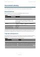


Table Of Contents
- Cambium PTP 700 Series User Guide
- Contents
- About This User Guide
- Contacting Cambium Networks
- Purpose
- Cross references
- Feedback
- Important regulatory information
- Radar avoidance
- USA and Canada specific information
- Renseignements specifiques aux USA et au Canada
- EU Declaration of Conformity
- Application firmware
- Specific expertise and training for professional installers
- Avoidance of weather radars
- External antennas
- Antennas externes
- Ethernet networking skills
- Lightning protection
- Training
- Problems and warranty
- Security advice
- Warnings, cautions, and notes
- Caring for the environment
- Chapter 1: Product description
- Overview of the PTP 700 Series
- Wireless operation
- Ethernet bridging
- TDM bridging
- System management
- FIPS 140-2 mode
- Chapter 2: System hardware
- Outdoor unit (ODU)
- Power supply units (PSU)
- Antennas and antenna cabling
- Ethernet cabling
- PTP-SYNC unit
- GPS receiver
- Network indoor unit (NIDU)
- Chapter 3: System planning
- Typical deployment
- Site planning
- Grounding and lightning protection
- Lightning protection zones
- Site grounding system
- ODU and external antenna location
- ODU ambient temperature limits
- ODU wind loading
- Hazardous locations
- PSU DC power supply
- PSU location
- PTP-SYNC location
- GPS receiver location
- NIDU location
- Drop cable grounding points
- LPU location
- Multiple LPUs
- Radio spectrum planning
- Link planning
- Planning for connectorized units
- Configuration options for TDD synchronization
- Data network planning
- TDM network planning
- Network management planning
- Security planning
- System threshold, output power and link loss
- Data throughput capacity tables
- Chapter 4: Legal and regulatory information
- Cambium Networks end user license agreement
- Definitions
- Acceptance of this agreement
- Grant of license
- Conditions of use
- Title and restrictions
- Confidentiality
- Right to use Cambium’s name
- Transfer
- Updates
- Maintenance
- Disclaimer
- Limitation of liability
- U.S. government
- Term of license
- Governing law
- Assignment
- Survival of provisions
- Entire agreement
- Third party software
- Compliance with safety standards
- Compliance with radio regulations
- Type approvals
- FCC/IC compliance
- FCC product labels
- Industry Canada product labels
- 4.9 GHz FCC and IC notification
- Utilisation de la bande 4.9 GHz FCC et IC
- 5.1 GHz FCC notification
- 5.2 GHz and 5.4 GHz FCC and IC notification
- Utilisation de la bande 5.4 GHz FCC et IC
- 5.8 GHz FCC notification
- 5.8 GHz IC notification
- 5.1 GHz band edge channel power reduction
- 5.2 GHz band edge channel power reduction
- 5.4 GHz band edge channel power reduction
- Réduction de puissance aux bords de la bande 5.4 GHz
- 5.8 GHz band edge channel power reduction
- Réduction de puissance aux bords de la bande 5.8 GHz
- Selection of antennas
- European Union compliance
- Cambium Networks end user license agreement

Chapter 3: System planning Data network planning
Data network planning
This section describes factors to be considered when planning PTP 700 data networks.
Ethernet interfaces
The PTP 700 Ethernet ports conform to the specifications listed in Table 58.
Table 54
PTP 700 Ethernet bridging specifications
Ethernet Bridging
Specification
Protocol IEEE802.1; IEEE802.1p; IEEE802.3 compatible
QoS Eight wireless interface priority queues based on these
standards: IEEE 802.1p, IEEE 802.1Q, IEEE 802.1ah, IEEE
802.1ad, DSCP IPv4, DSCP IPv6, MPLS TC, DSCP in PPP
Session Stage
Interfaces 100BASE-TX, 1000BASE-T, 1000BASE-SX, 1000BASE-LX
MDI/MDIX auto crossover supported
Max Ethernet frame size 9600 bytes
Service classes for traffic 8 classes
Practical Ethernet rates depend on network configuration and higher layer protocols. Over the
air throughput is capped to the rate of the Ethernet interface at the receiving end of the link.
Layer two control protocols
PTP 700 identifies layer two control protocols (L2CPs) from the Ethernet destination address of
bridged frames. The QoS classification can be separately configured for these protocols.
Table 55
Destination address in layer two control protocols
Destination address
Protocol
01-80-c2-00-00-00 to 01-80-c2-00-00-0f IEEE 802.1 bridge protocols
01-80-c2-00-00-20 to 01-80-c2-00-00-2f IEEE 802.1 Multiple Registration Protocol (MRP)
01-80-c2-00-00-30 to 01-80-c2-00-00-3f IEEE 802.1ag, Connectivity Fault Management (CFM)
01-19-a7-00-00-00 to 01-19-a7-00-00-ff Ring Automatic Protection Switching (R-APS)
00-e0-2b-00-00-04 Ethernet Automatic Protection Switching (EAPS)
Page 3-35