
User's Manual


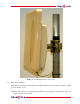
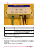
Table Of Contents

6
The OS-Gemini consists of a pair of identical devices that are deployed one at each end of the
link. At install time the user sets up one unit is set as the Master and the other as the Slave. Either
unit can be configured as master or slave.
Each end of the link consists of:
• An integrated outdoor transceiver unit containing all the radio and networking electronics.
Hereafter referred to as the Outdoor Unit (ODU).
• An indoor passive connection box containing status indicators, DC power connection and
network connection. Hereafter referred to as the Indoor Unit (IDU).
• A ‘mains’ power adaptor.
Power is fed into the IDU from the mains power adaptor via a standard low voltage DC connector.
The network connection is presented to the user at the IDU via an RJ45 socket. Connection
between the ODU and IDU is made using standard CAT 5 UV resistant cable. The spare twisted
pairs of the cable are used to feed power from the IDU to the ODU.
1.3.1 The Outdoor Unit (ODU)
The ODU is a self-contained unit. It houses both radio and networking electronics. The unit is fed
by a single CAT 5 UTP cable. Power is fed to the unit via the brown/brown-white pair connected
to pins 7 and 8 of the RJ45 plugs and sockets employed. It should be noted that this powering
arrangement is not standard Power-over-Ethernet (POE). The OS-Gemini ODU should only be
deployed using the supplied OS-Gemini Indoor Unit (IDU).
1.3.2 The Indoor Unit (IDU)
The OS-Gemini IDU is a passive device used to inject the DC supply voltage into the cable con-
necting the IDU to the ODU. The IDU also houses status indicators driven from the ODU over the
blue/blue-white pair connected to pins 4 and 5 of the RJ45 plugs and sockets employed.
The front panel contains indicators showing the status of the power and Ethernet connections.
• the power indicator is illuminated when the IDU is receiving 48 volts from the power adaptor.
• the Ethernet indicator illuminates when the ODU is powered; it flashes when there is Ethernet
activity.
The bottom of the IDU contains the Ethernet connection via RJ45 socket, the power connection,
an entry point for IDU-ODU cabling and the reset button.
The IDU also houses a reset switch. This reset switch is used for various purposes identified in
table 1.
reset IP switch