
User's Manual


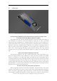
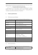
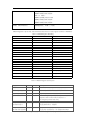
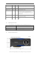
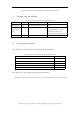
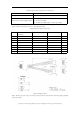
Table Of Contents

Cambricon Technologies, MLU270-F Series Intelligent Processing Card User Manual
Table8 Supported Auxiliary Power Connections
Users can use the CPU 8-Pin Power Socket within a Server directly, or use two 8-pin PCIe
Power Sockets, along with a One-To-Two Adapter Cable.
Table9 Adapter Cable Connections
Figure.5 Adapter Cable
Note: The first pin (Pin No.1) of every connector/socket should have obviously distinguishable
mark at the side.
Board Connector
Cable used
CPU 8-Pin
1× CPU 8-pin cable
CPU to PCIe 8-Pin Dongle Cable
2× PCIe 8-pin cable
2× PCIe 6-pin cable
1× PCIe 8-pin cable and 1× PCIe 6-pin cable
8-Pin CPU Power
connector
PCIe 8-Pin Socket 1
PCIe 8-Pin Socket 2
Colour
12V
5
3
Yellow
12V
6
1,2
Yellow
12V
7
3
Yellow
12V
8
1,2
Yellow
GND
1
7,8
Black
GND
2
5,6
Black
GND
3
7,8
Black
GND
4
5,6
Black