
User's Manual


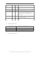
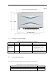
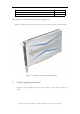
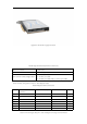


Table Of Contents

Cambricon Technologies, MLU270-X Series Intelligent Processing Card User Manual
Figure.5 Adapter Cable
Note: The first pin (Pin No.1) of every connector/socket should have obviously distinguishable
mark at the side.
Table 10Input Voltage Requirement
Power Supply
Min
Normal
Max
PCIe edge connector(12V)
11.04V
12V
12.96V
8pin connector(12V)
11.04V
12V
12.96V
PCIe edge connector(3V3)
3.0V
3.3V
3.63V
Table 11 Current Requirement
Power Supply
Peak Current
Moving Average
8pin connector(12V)
20A
200us
17A
1ms
13A
5ms
Table12 Power Capping
Power Capping Threshold
150W
Power Capping Response time (typical)
50ms
Power Capping Response time (max)
100ms
Table 13 Power Break
PB# PCIe pin assignment
B30
Power Brake response time(typical)
150us
PB# input insertion low time (min)
250ms
Power brake hardware slowdown factor
4x
GND
4
5,6
Black