2 azur 851E Your music + our passion ENGLISH Pre-Amplifier User's manual
Contents Important safety instructions......................................................................3 Limited warranty...........................................................................................4 Rear panel connections...............................................................................5 Front panel controls.....................................................................................6 Remote control.....................................................................
azur 851E ENGLISH Important safety instructions For your own safety please read the following important safety instructions carefully before attempting to connect this unit to the mains power supply. They will also enable you to get the best performance from and prolong the life of the unit: 1. Read these instructions. 2. Keep these instructions. 3. Heed all warnings. 4. Follow all instructions. 5. Do not use this apparatus near water. 6. Clean only with a dry cloth. 7.
Limited warranty Ventilation IMPORTANT – The unit will become hot when in use. Do not stack multiple units on top of each other. Do not place in an enclosed area such as a bookcase or in a cabinet without sufficient ventilation. Ensure that small objects do not fall through any ventilation grille. If this happens, switch off immediately, disconnect from the mains supply and contact your dealer for advice. Positioning Choose the installation location carefully.
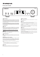
azur 851E Source 2 Source 1 GND 1 8 In Right (Balanced) Left (Unbalanced) Right Left (Balanced) Pre Out Right (Unbalanced) (Balanced) Left (Unbalanced) Source 5 Source 4 Left Right GND Rec Out 7 RS232C Mains Voltage Selector Switch: 100-120V/220-240V AC~50/60Hz 2 Rec In In Source 7 Out Source 6 In Source 3 Trigger Out IR Emitter Trigger Source 5 2 4 6 Control Bus Source 4 1 Off Designed and engineered in London, England L azur 851E Pre-Amplifier L 5 Power
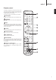
Front panel controls azur 851E Pre-Amplifier 7 10 1 Standby / On Phones Mode 1 2 3 Bass 4 5 Standby/On Switches the unit between Standby mode (indicated by dim power LED) and On (indicated by bright power LED). Standby is a low power mode where the power consumption is less than 0.5 Watts. The unit can be left in Standby mode when not in use.If the unit is not going to be used for a long period of time it should be switched off via the Power On/Off switch on the rear panel.
azur 851E The 851E is supplied with a CA System remote control that operates both this amplifier and Cambridge Audio 851 series and Stream Magic products. Insert the supplied AAA batteries to activate. The functions relevant to the amplifier are as follows: 1 1 Standby/On Switches the amplifier between On and Standby mode. 2 ENGLISH Remote control 2 Brightness Adjust the backlight of the front panel display; bright, dim or off. 3 Mute Mutes the audio on the pre-amplifier.
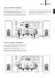
Source connections Power syncing (On/Standby control) Source 1, 2 and 3 on the 851E feature either unbalanced (phono/RCA) or balanced (XLR) connections. The 851E is designed to work at its highest performance when a balanced interconnect is used. When going in/out of Standby mode the Azur 851E pre-amplifier can (if desired) automatically control the 851W when connected via the Control Bus sockets (the Control Bus sockets are colour-coded orange on the rear panels of compatible Azur models).
azur 851E The diagram below shows the 851E connected to an 851W using the Balanced Audio inputs via three-pin XLR connectors. When using balanced (XLR) connections, the Left and Right Input Type switches on the 851W must be in the 'Balanced' position. Before making any connections to the loudspeakers, make sure all power is turned off and only use suitable interconnects (e.g. banana plugs). Ensure that the positive (+) and negative (-) connections are matched.
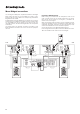
Mono Bridged connections The matching Azur 851W power amplifier features Mono and Bridged Mono settings that allow two (or more) 851Ws to be used as monoblocks for high end systems. Below is an example using two 851Ws in Bridged Mono with an 851E. In Bridged Mono mode each 851W drives one speaker across its output channels acting as a 500W mono amplifier instead of a 200wpc stereo one. One 851W drives the left speaker and the other the right.
851E Operating instructions Pre-amplifier setup The 851E has a custom-made display on the front of the unit that shows the current status and allows you to access the 851E System settings menu. Here you can adjust the listening settings of the amplifier to personal preference. The menu system is easy to navigate and control, simply by using the input select buttons to turn a feature on (solid circle) or off (no circle) and the volume control knob to increase/decrease settings.
Pre-amplifier setup continued Volume trim Volume ramp Display Mode Note: The Volume Trim menu item is hidden if the Fixed Volume is enabled. Sub LPF Power Vol Ramp Control Settings PP Mute Volume The 851E automatically ramps the volume down when going into Standby mode and up when coming out of Standby mode. To turn this feature off, press the Vol Ramp input select button in the System settings menu and set to off. Press the Mode button to exit the System settings menu.
851E Fixed volume Devices menu Any input of the 851E is able to be set for fixed gain. Whenever this input is selected the gain will automatically go to this value and will not be adjustable by the volume control. This can be useful with sources that have their own built in volume control (such as some set-top boxes etc.) Note: The Device menu item is hidden if the C-Bus is disabled.
Trigger In 2. W Overtemp – Over temperature detection In the System settings menu, press the Power input select button to enter the submenu. Press the Trig In input select button to enable the function. Indicator – Unit has switched off during operation. Mode Trig In Auto PwD Power Volume Description – CAP5 includes temperature detection which constantly monitors the heat generated by the output transistors.
Troubleshooting Control Bus The 851E features a Control Bus input/output that IR Emitter In In Out allow un-modulated remote control commands (positive logic, TTL level) to be received electrically by the unit and looped to another unit if desired. These control commands are typically generated by custom installation (multi-room) systems or remote IR receiver systems. The Control Bus sockets are colour-coded orange. There is no power RS232C Custom installation (C.I.
Cambridge Audio is a brand of Audio Partnership Plc Registered Office: Gallery Court, Hankey Place London SE1 4BB, United Kingdom Registered in England No. 2953313 © 2013 Cambridge Audio Ltd AP32333/1 www.cambridge-audio.