
User Manual


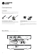


Table Of Contents

5
AXA35
Rear panel connections
A1
Power AC
USB 5V 500mA
Max Power Consumption: 260W
A2 A3 Phono A4 Rec Out
Ground
Ground
Designed & Engineered in Great Britain
Assembled in China
Left
Loudspeaker
Right
Loudspeaker
Left
Loudspeaker
Right
Loudspeaker
Mains Voltage Selector Switch
115V/220-230V AC ~ 50/60Hz
AXA35
Integrated Amplifier
Loudspeaker Terminals
Impedance: Nominal 8 ohms
1 2 3 5
4
7
6
1
AUDIO INPUTS(A1-A4)
These inputs are suitable for any ‘line level’ source equipment such as the audio
outputs of CD players, streaming devices such as a Chromecast Audio (RCA Phono
to jack cable required) etc.
2
PHONO INPUT
This unit also has a built in Phono stage.
Record players tted with Phono Cartridges of the Moving Magnet (MM) or high
output Moving Coil (MC) type (between 2-6mV output and 30-50k load impedance)
can be used.
Low output Moving Coil types (<1mV and usually 10-1000 ohm load impedance)
cannot be directly connected and will require a matching transformer or head amp.
Please consult your dealer for details.
Note: The ‘Ground’ terminals on both the record player and the AXA35 should be
connected (where possible) with a ground wire for lowest noise/hum pickup.
3
REC OUT
Connect to the recording input of a CD recorder input, tape deck or other compatible
recording device etc.
This output provides a constant high level output that does not uctuate with the
volume of the main unit. For this reason, the AXA35 cannot be used as a Preamplier
only or with a subwoofer.
4
USB POWER 5V 500mA
This USB connection is designed for charging or maintaining power to a device such
as a Streaming device or Bluetooth adaptor.
Note: This is not an input so will not allow you to play audio directly to the unit.
5
LOUDSPEAKER TERMINALS
Connect the wires from your left channel loudspeaker to the Left positive and
negative terminals and the wires from the right channel loudspeaker to the Right
positive and negative terminals.
In each case, the red terminal is the positive output and the black terminal is the
negative output.
Care should be taken to ensure no stray strands of wire are accidentally connecting
speaker outputs together as this may cause damage to the unit.
Please ensure that the loudspeaker terminals have been tightened adequately to
provide a good electrical connection. It is possible for the sound quality to be aected
if the screw terminals are loose.
6
VOLTAGE SELECT SWITCH
For servicing use only.
7
AC POWER SOCKET
Once all connections are complete, plug the AC power cable into an appropriate
mains socket and turn the unit on.
Please only use the power lead supplied with the unit.