
Operation Manual


5
CP1/CP2
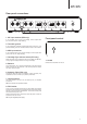
Rear panel connections
Front panel control
0dBL R
1
2
3
4
1
2
3
4
0.5 A
R L
MC MM Off On
R L
Turntable
Ground
Designed & Engineered in Britain
Assembled in China
MC
MM
Output
Cartridge Type Subsonic Filter
Balance
R L
12V
12V
1. MC input sockets (CP2 only)
If your turntable uses a moving coil cartridge, connect outputs here
(0.5-1mV, with 100 ohm, 220pF loading).
2. Turntable ground
If your turntable has a separate grounding lead then connect here. This
provides shielding to the arm and the sensitive circuitry in the turntable.
3. MM input sockets
If your turntable uses a moving magnet cartridge, connect outputs here
(3-5mV, with 47k ohm, 220pF loading).
4. Cartridge Type selector switch (CP2 only)
Match this switch to the cartridge type that your tunrtable uses. MM for a
moving magnet cartridge or MC for a moving coil cartridge.
5. Balance
This control allows you to make ne adjustments to the relative output
levels of the left and right channels. In the central position the output
from each channel is equal.
6. Subsonic Filter (CP2 only)
The subsonic lter cuts out very low frequency ‘rumble’, caused by vinyl
imperfections, which can aect your system’s performance.
7. Output sockets
Use phono cables to connect to any line level input on your amplier,
such as Aux.
NB. Do not connect to a phono level input.
8. PSU socket
Once you have completed all connections to the amplier and turntable,
plug the PSU power cable into an appropriate mains socket and switch
the unit on via its front panel On/O button. The LED on the front panel
will indicate that the power is on.
Please note the 651P has an output relay, which after power on takes 15
seconds to come out of mute.
NB. Only use supplied power supply.
1. On/O
Switches the unit between on and o.
1
1
2 3 4 5 6 7 8