User Manual
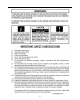
TABLE OF CONTENTS Introduction ................................................................4 INTRODUCTION Carton Contents..........................................................5 Thanks for choosing the MicroWorks II Multimedia Setup Options..........................................................6-7 Speaker System. It features the finest drivers, precision Connection Diagram ..............................................
CARTON CONTENTS A) Two Satellite Loudspeakers B) Desktop Stands,Thumb screws (installed on satellites) B A C) Wallmount hardware, Self-adhesive Feet D) Hook and Loop fastener (for volume control, if not used on Desktop Stand) E) One Subwoofer/Amplifier Loudspeaker F) Power Adapter (AC to AC) G) Volume On/Off Control H) 2 Satellite Connection Cables (2-meters) C No.
SETUP OPTIONS Cambridge SoundWorks, Inc. supplies screws and plastic anchors for convenience, but it is the speaker purchaser’s responsibility to insure that any speaker mounting or placement is secure, stable and reliable. Cambridge SoundWorks assumes no responsibility for damage to its products or any damage to property resulting from speaker A positioning or placement. SUBWOOFER/AMPLIFIER The Subwoofer/Amplifier requires no assembly.
Wall Mounting With A Swivel Bracket Contact Cambridge SoundWorks about available swivel brackets. F) Follow the installation instructions for your particular mounting bracket to attach it to a flat surface. If desired, you can install the whole bracket/satellite assembly inverted. This places the bracket above the satellite, concealing it when viewed from below. In this case, remove, invert and re-install the the F satellite grille to position the logo correctly.
CONNECTION DIAGRAM Right Speaker RED Headphones connect to the Volume On/Off control MicroWorks II Volume Control MusicWorks Connect the blue miniplug to INPUT A. AUDIO OUT Computer sound card Insert the green miniplug into your primary music source’s stereo minijack output (a sound card, a stereo TV or a Cambridge Connect a second sound source with a variable output to INPUT B.
Left Speaker RED MicroWorks II Subwoofer Input Panel RED RED R - R + - L + Music er 9
POSITIONING YOUR SPEAKERS SUBWOOFER/AMPLIFIER Place the Subwoofer cabinet on the floor, preferably near a wall. Do not place it on a desktop or shelf. For the most efficient bass performance, place the subwoofer near a corner. If the subwoofer is placed away from the intersection of two room surfaces, the maximum bass output will be reduced. Use the Bass Level control to adjust the bass output to your desired balance. Recommended Bass control settings for each type of location are shown.
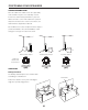
POSITIONING THE SATELLITES Wall Placement (Swivel brackets available separately) Avoid facing a satellite parallel to a nearby wall (within 6-8 inches). The reflected sound from the wall A degrades the sound coming directly from the satellite (diagram A). Try to position wall-mounted satellites so both are approximately at your ear level while sitting or slightly OK higher. Make sure the speakers form at least a 20degree angle with your listening position.
CONNECTIONS Volume On/Off Control A) If you are using the Desktop Stand, slide the Volume Control onto the support strut on one of the stands. A B) The BLUE miniplug of the Volume On/Off Control should be inserted into the subwoofer minijack “A” labeled “TO VOLUME CONTROL.” Signal Connections C) The GREEN miniplug of the Volume On/Off Control should be connected to your primary audio program source. INPUT B is a second audio input that blends with INPUT A. Connect a second audio program source here.
Other Connection Situations d) If you connect the MicroWorks II to a television with 1) Using the MicroWorks II as a high performance stereo variable audio outputs, you can still use your televi- television sound system. sion's remote control to adjust overall output. Set a) A stereo television with audio signal output typically the MicroWorks II Volume On/Off control at the 12 has two RCA-type jacks (one red, one white). To o'clock position.
2) Using the MicroWorks II as a sound system for a component CD player. COMPONENT CD OUTPUT Typically, there are two RCA-type jacks (one red, one white) on the CD player. To connect to these jacks, obtain a stereo signal cable with two RCA OUT plugs on one end and a 3.5 mm stereo minijack at RIGHT LEFT the other end. Connect the RCA plugs to the RCA jacks on the player. Connect the Volume On/Off Control green miniplug to the minijack of the adapter. Signal Cable One 3.
Speaker Connections To connect the 2-meter speaker cables (two wires at each end): Push back the red speaker input tab on a satellite, exposing the wire hole. Fully insert one of the wires with a red band into the wire hole and release the tab. Repeat the procedure with the adjacent speaker wire and the black speaker input tab on that speaker. Connect the two wires at the other end of that same speaker cable to the red and black “R” speaker input tabs on the subwoofer.
OPERATION AND FINAL ADJUSTMENT 1) Use the Volume Control or the signal source control to vary output level. 2) Defeat or cancel any “tone control” or other sound adjustments within your audio program source. Portable CD players may have “bass boost” switches and many computer sound programs have audio adjustments concealed in drop-down menus. 3) If possible, play a variety of musical CDs with good deep bass content to judge the best setting of the SUBWOOFER LEVEL control.
SPECIFICATIONS Analog Input: 775 millivolts for full output 10 kohms input impedance Amplifiers: Satellite: 20 watts continuous at 1 kHz, two channels driven at less than .1% total harmonic distortion. Subwoofer: 40 watts continuous at 100 Hz, one channel driven at less than .3% total harmonic distortion. System Frequency response: Satellite: 150 Hz to 15 kHz, +/- 3 dB Subwoofer: 45 Hz to 150 Hz +/- 3 dB Drivers: Nominal 6.5 inch subwoofer driver with 8 inch passive radiator Nominal 3.
CAMBRIDGE SOUNDWORKS, INC.