IMPORTANT If you have any problems with this product (missing or damaged parts, assembly issues, etc.), PLEASE DO NOT RETURN TO THE RETAILER/STORE from where you purchased the product. Please call our Toll‐Free Customer Service Hotline at: 1‐800‐416‐3511 Between 9:00 AM and 5:00 PM Eastern Time, Monday through Friday To expedite any future warranty claims, please retain the Instruction Sheet, Warranty Card and receipt for future use.
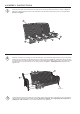
ASSEMBLY INSTRUCTIONS 1 Attach the seat frame to the back frame by using four 5/16"x40 mm bolts and washer as shown in Figure 1. Guide these bolts through the holes in the seat frame, into the fixed nuts already in place in the back frame. Do not over tighten. A G F H B 2 Attach love seat arm by inserting two 5/16"x25 mm bolts with washers through the holes in front seat portion of the love seat frame and into the holes in the love seat arm shown in Figure 2.
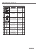
PARTS IDENTIFICATION LIST * NOTE: PARTS SHOWN ON PARTS LIST ARE NOT TO SCALE PARTS LIST DESCRIPTION ORDER PART # QTY A BACK FRAME SK0939 1 B SEAT FRAME SK0940 1 C LEFT ARM SK0941 1 D RIGHT ARM SK0942 1 E 5/16" X 25 MM BOLT HW0186 4 F 5/16" X 40 MM BOLT HW0275 8 G Ø8.5 X 1.
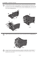
ASSEMBLY INSTRUCTIONS 1 Assemble furniture on a smooth, non-abrasive surface. Attach the back frame to right arm by using two 5/16"x40 mm bolts and washers as shown in Fig.1 . Guide the bolts through holes in back frame, into pre-drilled holes in the right arm . Hand tighten only. Attach the seat frame to right arm and back frame by using four 5/16"x25 mm bolts and washers as shown in Fig.2 . Hand tighten only.
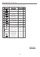
PARTS IDENTIFICATION LIST * NOTE: PARTS SHOWN ON PARTS LIST ARE NOT TO SCALE PARTS LIST DESCRIPTION ORDER PART # QTY A SEAT FRAME SG0154 1 B BACK FRAME SG0155 1 C LEFT ARM SG0156 1 D RIGHT ARM SG0157 1 E GLIDER BASE W/ GLIDER BRACKET SG0158 SG0159 1 F 5/16" X 25 MM BOLT HW0186 6 G 5/16" X 40 MM BOLT HW0275 8 H Ø8.5 X 1.5 MM WASHER HW0005 14 I BOLT COVER HW0105 14 J HEX BOLT DRIVER HW0006 1 GLIDER BRACKET G0080 ST4.
ASSEMBLY INSTRUCTIONS CSA Model 98910 ARL11103 Installer: Leave these instructions with consumer. Consumer: Keep these instructions for future reference. DANGER If you smell gas: 1. Shut off gas to the appliance. 2. Extinguish any open flame. 3. If odor continues, keep away from the appliance and immediately call your gas supplier or fire department. WARNING: Improper installation, adjustment alteration, service or maintenance can cause injury or property damage.
IMPORTANT SAFETY INFORMATION The installation must conform with local codes or, in the absence of local codes, with the National Fuel Gas Code, ANSI Z223.1/NFPA 54; International Fuel Gas Code. ; Natural Gas and Propane Installation Code, CSA B149.1; or Propane Storage and Handling Code, B149.2, as applicable. The appliance and its appliance main gas valve must be disconnected from the gas supply piping system during any pressure testing of that system at test pressures in excess of 1/2 psi (3.5kPa).
IMPORTANT SAFETY INFORMATION ABOUT PROPANE (LP) GAS A self contained LP-gas cylinder for use with this appliance must have a capacity of 20 lbs. and must be equipped with a Type 1 connector and an OPD (overfill protection device). See Figure 1. The LP-gas supply cylinder to be used must be constructed and marked in accordance with the specification for LP-gas cylinders of the U.S.
PARTS IDENTIFICATION LIST PART DESCRIPTION PART# QTY A CONTROL KNOB FP0245 1 B GAS VALVE FP0307 1 C THERMOCOUPLE FP0004 1 D LP REGULATOR HOSE FP1369 1 E ELECTRODE FP1375 1 F GAS TUBE FP0309 1 G ORIFICE ELBOW FP1385 1 H IGNITION MODULE FP0006 1 I ORIFICE BRACKET FP0311 1 J PROPANE ORIFICE FP1283 1 K NATURAL GAS ORIFICE FP1284 1 L LP TANK RETAINING KNOB FP0585 2 M “AAA” BATTERY(1.
INSTALLATION 1. With the help of another person, turn the table base assembly in the upright position. Carefully place the table top (not included) onto the table base. After making any necessary adjustments to the alignment of the table top and firepit base, use bolts and washers as shown in Figure 3. Guide the bolts through the holes in the base brackets, into the pre-drilled holes in the table top. Do not tighten completely. Repeat on other three sides.
3. Remove the cardboard cover from the ignition well as shown in Figure 5. Remove any lava rock or fire ice on top of ignition well. Figure 5 Cardboard Cover 4. Lift off the tank door, place the tank in the holder and use the chain to hold the tank. Connect the regulator as shown in Figure 6. Turn the black handle clock-wise to tighten. Turn the handle counterclock-wise to remove. The hose must point down.
NATURAL GAS CONVERSION Natural gas conversion must be performed only by your natural gas provider or service company. 1.Disconnect the regulator hose from the gas valve. See Figure 8. Figure 8 2.Disconnect the gas tube from the orifice elbow. Remove the two M4 nuts and remove the orifice holder. Replace the propane orifice with the natural gas orifice from the kit and reinstall the orifice holder. Apply a solution of soapy water to all connections to check for leaks.
LIGHTING INSTRUCTIONS 1. Locate the control and igniter panel. Make sure the control knob is in the “OFF” position. See Figure 10. Open the tank door and open the tank valve all the way. 2. Push in the igniter button. You will hear a slight clicking sound. With the igniter button pushed in, push and turn the control knob to the “ON” position. The fire should light within a few seconds. Once the flame is lit, release the igniter button and continue to hold the control knob in for 10 to 15 seconds.
TROUBLESHOOTING GUIDE PROBLEM CAUSE REMEDY No Propane Gas at Burner Check that gas tank valve is open. Turn control knob to “ON” and push control knob in. Make sure tank has propane gas. Burner won’t light No Spark at Electrode Burner won’t stay lit after lighting Check that AAA battery is installed with negative (-) end first and has a charge. Check that the wire is connected to the ignition module. Check that the electrode is not cracked or broken.