PRESSURE / VACUUM BLOWER PACKAGE INSTRUCTION, OPERATIONS & MAINTENANCE MANUAL CAMCORP, Inc. Phone: 913-831-0740 ~ Fax: 913-831-9271 www.camcorpinc.
TABLE OF CONTENTS General Information -------------------------------------------------2 Principle of Operation -----------------------------------------------3 Installation ------------------------------------------------------------4 Start-Up------------------------------------------------------------- 5-6 Maintenance ----------------------------------------------------------7 Troubleshooting ------------------------------------------------------8 NOTE: It is the owner’s responsibility to maintain the s
GENERAL COMMENTS: CAMCORP supplies air pump packages comprised of positive displacement blowers manufactured by various companies. A Service Manual for your specific blower is included as an inset in this manual. For specific maintenance and lubrication information, please refer to this insert. -READ & UNDERSTAND SAFETY DECALSInstallation and Operation Cautions: Be sure that the motor is wired for correct rotation; some models of blower are unidirectional and damage could occur if rotation is reversed.
PRINCIPLE OF OPERATION CAMCORP blower packages are set up to provide air to a pressure conveying system or vacuum required for a negative pressure system. Typically the positive displacement blower used on such a package is not capable of supplying air to a pressure higher then 15 psig or vacuum greater then 14” Hg. Depending on the specific blower, it may have a maximum pressure or vacuum capability of somewhat less than that.
INSTALLATION CAMCORP’s positive displacement blower package consists of a positive displacement blower, a vertical or horizontal frame assembly, a motor, take-up table, or motor slide rails, V-belt drive and belt guard, an air intake or inline filter, intake and discharge silencer, a pressure or vacuum relief valve preset at the maximum pressure or vacuum rating of the blower, flexible connections, a check valve (pressure blower assemblies only), pressure/vacuum gauge and pressure or vacuum switch.
LOCKOUT / TAGOUT BEFORE PRE – STARTUP CHECK PRE – START-UP CHECK LIST: A. Check alignment of the drive and tension of the belts. B. Make sure that the blower and all conveying lines are free of foreign material. C. Check pressure relief valve to be sure they are unrestricted. D. Check that the blower has been properly lubricated according to the manufacturers insert. E. Check the breather-filters on the blower for proper installation. F.
E. Check the amp draw of the motor to be sure that the full load amp rating is not exceeded. See motor nameplate. ! Do not operate blower beyond manufacturers recommended limits. ! Be aware that there are also minimum recommended RPM limitations below which adequate lubrication will not be maintained. ! Consult the manufacturers insert or factory for the specific limits for this blower. 6 CAMCORP, Inc. Phone: 913-831-0740 ~ Fax: 913-831-9271 www.camcorpinc.
MAINTENANCE A. Check oil level daily B. Refer to the general lubrication guidelines in this manual for recommended frequency of oil change and type of oil. For more specific information on blower maintenance and lubrication see the manufacturer’s insert (manual) accompanying this manual. C. Clean the intake or inline filter every 40 hours or more often if dust conditions are severe. The filter element is washable using luke warm water with mild detergent. D.
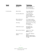
TROUBLESHOOTING POSITIVE DISPLACEMENT ROTARY BLOWERS Symptom Possible Causes Possible Sources Noisiness Rotor-to Rotor Contact Rust Build up or Rotors Rotors Our of Time Excessive Pressure Ratio Failed Bearings (s) Failed Gears Failing Bearing (s) Faulty Installation Non-spec Oil Contaminated Oil Insufficient Oil Improperly Mounted Sheave Over-tightened Belts Failing Gears Insufficient Backlash Non-spec Oil Contaminated Oil Insufficient Oil Sever Torsional Vibration Failing Lubricated Coupling or
Symptom Poor Performance Possible Causes Possible Sources Belt Flutter Insufficient Static Tension Sheave Misalignment Sever Torsional Vibration Restricted Inlet Clogged Filter Element Collapsed Inlet Hose Down Stream Restriction Clogged Dust Filter Undersized Dust Filter Faulty Check Plate Improperly Installed Check Plate Erroneous Pressure or Vacuum Indication Loose Gauge Connection Gauge Movement Damaged Gauge Inaccurately Calibrated Air Leakage Improper Relief Valve Setting Blown Gaskets Lo
Symptom Possible Causes Possible Sources Leaking Oil Failed Oil Seals Foreign Material in Seal Bores Faulty Installation Non-spec Oil Contaminated Oil Overheated Rotor Shafts End Cover Seams Not Tight Bolts Loose Gaskets Torn Oil Foaming Non-spec Oil Oil Cavities Overfilled Excessive Motor Amperage Excessive Pressure Ratio Excessive Pump Speed Line Voltage Drop Air Density Increase Loose Electrical Connections Foreign Material in Air Box Chronic Fuse Blowing or Circuit Breaking Underrated Fuses
Pressure and vacuum switches contain one or two single pole, double throw switches rated (continuous inductive) for 10 amps at 125 or 250 volts or 3 amps at 480 volts. The installation and use of this electrical apparatus must be in accordance with the national electrical code and any other applicable local codes and ordinances. Standard motors supplied by CAMCORP will be 230/460 volt, 3 phase, 60 cycle and control circuits will be 110 volt, single phase, 60 cycle.
M-D Pneumatics™ Rotary Positive Displacement Air Blower Models EQUALIZER DF™ 4504 4506 4509 4512 4612 EQUALIZER RM™ 4604 4606 4609 6012 6016 6024 INSTALLATION OPERATION MAINTENANCE REPAIR Model 4600 Equalizer RM Model 4500 Equalizer DF MANUAL WARNING DO NOT OPERATE BEFORE READING MANUAL.
SAFETY INSTRUCTIONS 1. Do not operate before reading the enclosed instruction manual. 2. Use adequate protection, warning and safety equipment necessary to protect against hazards involved in installation ! WARNING ! Keep body and clothing away from machine openings WARNING Hearing Protection Required ! ! WARNING Do not operate without guards in place CAUTION Do not touch hot surfaces SAFETY WARNING • Keep hands and clothing away from rotating machinery, inlet and discharge openings.
TABLE OF CONTENTS SECTION PAGE SAFETY INSTRUCTIONS & WARNING TAGS 2 SAFETY PRECAUTIONS 3 INTRODUCTION 4 OPERATING DATA 4 INSTALLATION 5 LUBRICATION & OIL RESERVOIR CAPACITIES 6 FLOW CONFIGURATION 6 PREVENTATIVE MAINTENANCE / STARTUP CHECKLIST 7 TROUBLESHOOTING 8 RECOMMENDED SHUTDOWN PROCEDURE / FLOW DIRECTION BY ROTATION 9 DISASSEMBLY & INSPECTION 10 ASSEMBLY 11 SPECIAL TOOL DRAWINGS - MODELS 4500 / 4600 13 SPECIAL TOOL DRAWINGS - MODEL 6000 14 MAINTENANCE & SERVICE SPECIFICATI
INTRODUCTION CONGRATULATIONS on your purchase of a new EQUALIZER® Rotary Positive Displacement Air Blower from Tuthill Vacuum & Blower Systems. Please examine the blower for shipping damage, and if any damage is found, report it immediately to the carrier. If the blower is to be installed at a later date make sure it is stored in a clean, dry location and rotated regularly. Make sure covers are kept on all openings. If blower is stored outdoors be sure to protect it from weather and corrosion.
INSTALLATION WARNING: Customers are cautioned to provide adequate protection, warning and safety equipment necessary to protect personnel against hazards involved in the installation and operation of this equipment in the system or facility. Do not use air blowers on explosive or hazardous gases. Each size blower has limits on pressure differential, running speed, and discharge temperature, which must not be exceeded. These limits are shown on the table "Maximum Operating Limits” on page 15.
LUBRICATION Every M-D Pneumatics™ blower from Tuthill Vacuum & Blower Systems is factory tested, oil drained and shipped dry to its installation point. Both independent oil reservoirs must be filled to the proper level before operation. Shaft bearings at the gear end of the blower are splash lubricated by one or both gears dipping into an oil reservoir formed in the gear end plate and cover. Shaft bearings at the drive end of the blower are lubricated by a slinger assembly dipping into an oil reservoir.
PREVENTATIVE MAINTENANCE A good maintenance program will add years of service to your blower. A newly installed blower should be checked frequently during the first month of operation, especially lubrication. Check oil level in both the drive end and gear end of the blower and add oil as needed. Complete oil changes are recommended every 1000 operating hours, or more frequently depending on the type of oil and oil operating temperature. The following is recommended as a minimum maintenance program.
TROUBLESHOOTING Although EQUALIZER® blowers are well designed and manufactured, problems may occur due to normal wear and the need for readjustment. The chart below lists symptoms that may occur along with probable causes and remedies. SYMPTOM PROBABLE CAUSE REMEDIES Loss of oil. Gear housing not tightened properly. Tighten gear housing bolts. Lip seal failure. Disassemble and replace lip seal. Insufficient sealant. Remove gear housing and replace sealant.
RECOMMENDED SHUTDOWN PROCEDURE TO MINIMIZE RISK OF FREEZING OR CORROSION When high humidity or moisture is present in an air piping system, condensation of water can occur after the blower is shut down and the blower begins to cool. This creates an environment favorable to corrosion of the iron internal surfaces, or in cold weather, the formation of ice. Either of these conditions can close the operating clearances, causing the blower to fail upon future start-up.
DISASSEMBLY & INSPECTION With proper maintenance and lubrication, normal life expectancy for gears, bearings, and seals can be achieved. However, over a period of time these parts must be repaired or replaced to maintain the efficiency of your blower. This section is written in a way that will allow you to completely disassemble your blower. The inspection of certain repairable or replaceable parts is referred to at the point of disassembly where these parts are exposed.
Assembly of Blower The assembly procedure is generally the same for all series, but where there are differences, notations are made. Dowel pins are used to locate end plates, housing and end covers in their proper location relative to each other. Be sure they are in place. It is recommended that the gear end rotor shaft bearings be purchased from Tuthill Vacuum & Blower Systems, as they are specially ground to locate the rotors with correct end clearance relative to the gear end plate.
6. Install keys [24] in rotor shaft keyways. Tight fits are required. 7. Lubricate shafts and keys and press drive gear (right hand helix) on drive rotor. To install driven gear, align reference marks as shown in Fig. 6B. Tap gear with mallet to start then press the gear until seated. NOTE: All timing gears must be used in sets as they are matched and serially numbered. 8.
When removing gear shell from driven gear, it is not necessary to remove gear lock bolt. After completing the timing of the lobes bend over lock tabs on the four gear cap screws. 19. Install gear cover [7] using same method as was used to install drive cover. (Step 18). 20. Install mounting feet [304] and secure with cap screws and washers [307 & 80]. 21. Prior to putting blower into operation, follow Installation and Operation instructions.
14 All dimensions shown are in inches.
MAINTENANCE AND SERVICE SPECIFICATIONS SHEET RECOMMENDED LUBRICANTS AND CAPACITIES RECOMMENDED MINERAL BASED LUBRICANTS AMBIENT TEMPERATURE SHELL CITGO CHEVRON TEXACO EXXONMOBIL 0o F (-18o C) to 32o F (0o C) TELLUS® PLUS 68 (ISO 68) A/W 68 (ISO 68) RANDO HD 68 (ISO 68) DTE HEAVY MEDIUM (ISO 68) 32o F (0o C) to 90o F (32o C) TELLUS® PLUS 100 (ISO 100) A/W 100 (ISO 100) RANDO HD 100 (ISO 100) DTE HEAVY (ISO 100) 90o F (32o C) to 120o F (50o C) TELLUS® PLUS 150 (ISO 150) A/W 150 (ISO 150) RAN
CUTAWAY VIEW - MODELS 4504, 4506, 4509, 4512 When ordering parts, use the item number shown, plus your model and serial number. TORQUE CHART ITEM PART 16 lbf-ft (N-m) 26 Cap Screw M10 x 1.5 20-29 (27-39) 29 Cap Screw M14 x 2 57-85 (77-115) 62 Cap Screw M8 x 1.25 9-14 (12-19) 307 Cap Screw M12 x 1.
PARTS LIST - MODELS 4504, 4506, 4509, 4512 When ordering parts, use the item number shown, plus your model and serial number.
CUTAWAY VIEW - MODELS 4604, 4606, 4609, 4612 When ordering parts, use the item number shown, plus your model and serial number. TORQUE CHART ITEM PART MODEL 4600 MODEL 4600D 18 lbf-ft (N-m) 26 Cap Screw M10 x 1.5 20-29 (27-39) 29 Cap Screw M14 x 2 57-85 (77-115) 40 Cap Screw 5/8”-11 UNC 90-120 (122-163) 62 Cap Screw M8 x 1.25 9-14 (12-19) 307 Cap Screw M12 x 1.
PARTS LIST - MODELS 4604, 4606, 4609, 4612 When ordering parts, use the item number shown, plus your model and serial number.
CUTAWAY VIEW - MODELS 6012, 6016, 6024 When ordering parts, use the item number shown, plus your model and serial number. TORQUE CHART ITEM PART 20 lbf-ft (N-m) 26 Cap Screw M10 x 1.5 20-29 (27-39) 29 Cap Screw M14 x 2 57-85 (77-115) 62 Cap Screw M8 x 1.25 9-14 (12-19) 307 Cap Screw M12 x 1.
PARTS LIST - MODELS 6012, 6016, 6024 When ordering parts, use the item number shown, plus your model and serial number.
WARRANTY Subject to the terms and conditions hereinafter set forth and set forth in General Terms of Sale, Tuthill Vacuum & Blower Systems (the seller) warrants products and parts of its manufacture, when shipped, and its work (including installation and startup) when performed, will be of good quality and will be free from defects in material and workmanship.
NOTES IMPORTANT All M-D Pneumatics™ blowers manufactured by Tuthill Vacuum & Blower Systems are date coded at time of shipment. In order to assure you of the full benefits of the product warranty, please complete, tear out and return the product registration card below, or you can visit our product registration web page at http://pneumatics.tuthill.com/product_registration IMPORTANT All M-D Pneumatics™ blowers manufactured by Tuthill Vacuum & Blower Systems are date coded at time of shipment.
NO POSTAGE NECESSARY IF MAILED IN THE UNITED STATES BUSINESS REPLY MAIL FIRST-CLASS MAIL PERMIT NO.