Installation, Operation, & Maintenance Manual CAMCORP CamAiro Vertical Cartridge Dust Collector Unique Design & Engineering Approaches for Industrial Applications
Safety Recommendations ............................................................................ 1-1 Receiving & Inspection of the Unit............................................................. 2-1 Storage Recommendations .......................................................................... 2-2 Setting Up Your Unit................................................................................... 3-1 Filter Cartridge Installation .................................................................
! " Dust Collector.............................................................................................. 6-1 Timer............................................................................................................ 6-5 Compressed Air System .............................................................................. 6-6 # Routine Maintenance ................................................................................... 7-1 $ % & Dust Collector Terms & Definitions ................
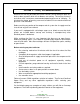
Section 1 – Safety Recommendations Because this unit may be under pressure or vacuum, do not attempt to open any device, doors or panels while fans or blowers are running. The unit has air hoses and valves with a maximum recommended operating pressure of 100 psig. To eliminate the danger of bursting, care must be taken to insure maximum desired pressure is not exceeded. Before servicing any portion of the compressed air system the air supply must be shut off and any pressure relieved.
Section 2 - Receiving ' ( ) *+ ,- Prior to accepting the shipment(s) care must be taken to inspect all equipment received both for proper count and for damage. Any and all irregularities must be noted on the carrier’s copy of the shipping receipt to assist in settling any claims for damage or shortages. All equipment is shipped FOB point of origin whether on a prepaid or collect freight basis. ANY CLAIM FOR DAMAGE IN TRANSIT OR SHORTAGES MUST BE BROUGHT AGAINST THE CARRIER BY THE PURCHASER.
01( -- 21 . Baghouse, Bin Vent, Filter Receiver, Dirty Air Hopper and Housing • • • • Housing can be stored outside. Equipment must be blocked up to keep the flanges out of the dirt. Most units are supplied with a plain unfinished interior. If storage of more than two weeks is anticipated the interior should be prime coated before storage.
01( -- 21 .3 + 24 Accessory Parts • • This includes all gauges, nylon or copper tubing, valves, gaskets and other parts not specifically called out. These items should be stored inside a cool dry place protected from moisture, insects, and rodents. Fan and Fan Accessories • • • Fans can be stored outside on a pallet or skid to keep them out of water and dirt. Fan silencers, outlet dampers, and inlet boxes should also be tarped and stored on a pallet or skid.
01( -- 21 .3 + 24 Isolation Dampers • • All limit switches, solenoids, and air cylinder ports must be capped and taped to prevent any moisture or dirt from entering. Equipment can sit outside provided it is covered with a tarp and is on a pallet or skid to keep it out of water and dirt. Rotary Valve • • • Rotor and interior of valve should be well oiled with vegetable oil to prevent rust and to maintain compatibility with product.
Section 3 - Installation ( !, +0! CAMCORP dust collectors are shipped either in one piece, fully assembled, or in two or more sections depending on the unit size and weight. Before attempting to move the dust collector or any of its sections review both the certified general assembly drawing supplied from CAMCORP and the rigging and lifting guidelines included in this manual.
( !, +0! 3 + 24 Step 4: Platform and ladder, if applicable, can now be attached. Torque the fasteners to the appropriate specifications. All CAMCORP dust collectors are provided with lifting lugs for ease in handling of the units during field erection and installation. The number and location of these lifting lugs will vary depending on the model, size, and weight of the dust collector.
( !, +0! 3 + 24 Compressed Air Manifold: Typically, CAMCORP ships the compressed air manifold installed complete with diaphragm valves and solenoid enclosure(s), except when units are over legal shipping width with them in place. Flanges: All bolts on flanges should be tight. All ports in the dust collector not being used must be plugged prior to start-up.
( !, +0! 3 + 24 The firing sequence of the diaphragm valves on the dust collector should be set so that no two adjacent rows of cartridges fire in succession (if possible) to insure maximum cleaning and life of the filter media. This can only be achieved when wiring the pulse timer board to the solenoid valves. Apply electrical power to the smart timer and make sure that it is cycling completely through all rows of the unit. This will only happen when the smart timer is put into manual mode.
Auxiliary Equipment: All auxiliary equipment must be installed according to its manufacturer’s specifications and interlocked with the entire system as needed. Direction of rotation of each item must be checked prior to start-up of the entire system. 3-5 CAMCORP, INC. Phone: 913-831-0740 Fax: 913-831-9271 www.camcorpinc.
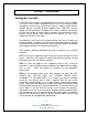
• • • Open the access door on the dust collector. Depending on the size of your dust collector, there are a number of rails or carriage assemblies attached to the bottom of the tube sheet for the filter cartridges to be support from. The handle levers for each rail should be pushed forward, which lowers them and allows the filter cartridges to be either installed or removed. 3-6 CAMCORP, INC. Phone: 913-831-0740 Fax: 913-831-9271 www.camcorpinc.
• • • • The filter cartridges have a metal mounting flange around the top of them. If the dust collector requires over bags, they should be installed before installing the filter cartridges into the dust collector. Pick-up the filter cartridge(s) and slide the metal pan over the top of the lowered rails of the carriage assembly. Be careful not to damage the filter media when handling them. Push the cartridges toward the back of the dust collector as far as possible. 3-7 CAMCORP, INC.
• • • After the filter cartridge(s) are all slid in, grab both lever arms and pull forward. Be careful again to not damage the filter media. The levers will raise the filter cartridge(s), making them seal against the tube sheet. Reverse this procedure to uninstall the cartridges. 3-8 CAMCORP, INC. Phone: 913-831-0740 Fax: 913-831-9271 www.camcorpinc.
Section 4 - Operation , 01 A. B. C. D. ( 0 ,5 Solids laden air or gases enter the unit at the hopper or housing inlet. Air passes through the filter media. Solids are retained on the filter media surface. Cleaning cycle consists of a momentary blast of 80-90 psig compressed air: 1. Momentarily taking a row of cartridges off stream through pressure reversal. 2. Flexing filter cartridge media. 3. Solids are released to fall towards hopper and through rotary valve or other discharge equipment.
10 !, ) 65. Installation Make sure the unit is secured to the floor or mounting surface. The ladder(s) and platform(s) must be tightened and set up according to OSHA requirements. Ducting and piping must be secured and routed out of the way of traffic whenever possible to avoid injury. Ducting must also be free of all debris including moisture. Interior of Dirty Air Plenum Inspect the filter cartridges, referring to the “Filter Cartridge Installation” section of this manual.
10 !, ) 65. 3 + 24 Explosion Relief Panels – Shear Bolt Style (when used) Inspect explosion relief vents (when used) for broken or damaged explosion bolts. ASSURE THAT THERE ARE NO STEEL BOLTS USED FOR THE INSTALLATION OF THE EXPLOSION RELIEF PANEL!!! These bolts are made of special high tech poly-vinyl chloride and are designed to relieve at a specific pressure. A magnet should be used to check for steel bolts.
10 !, ) 65. 3 + 24 With the compressed air system operating, energize the smart timer board to begin pulsing. The smart timer must be put in manual mode. Check to see that all solenoids are firing by placing a finger over the exhaust port of one of the solenoid valves. When the solenoid valve being checked is energized by an electrical pulse from the timer board the finger at the exhaust port should feel a short blast of air.
10 !, %+. 0 5 7. - . Fan or Blower System Start the fan or blower and check for proper rotation. Check dust pickup points for proper suction. Balance airflow in individual ducts. Check for air leakage at all flanged connections. Equipment Start-Up Sequence The compressed air supply system must be started first. When the pressure gauge on the compressed air manifold indicates that the system is at full pressure (80-90psig) the pulse timer can be energized.
)+ 2 8 0 2+0 . Dust control systems Reverse start-up procedure, shut down fan, then after a 5 or 10-minute delay, shut down the timer and discharge system. Pneumatic systems Reverse start-up procedure, shut down fan, then after 5 or 10 minute delay, shut down the timer and discharge system. 4-6 CAMCORP, INC. Phone: 913-831-0740 Fax: 913-831-9271 www.camcorpinc.
Section 5 - Component Information The following pages show details of the mechanical and electrical components of a typical dust collector. Below is information for identifying each component and repair kit if applicable. Dwyer Magnehelic Differential Pressure Gauge Camcorp part number 400031 – Range: - 15” w.c.
Explosion Vents (if applicable) - Confirm Vent(s) with Camcorp Camcorp P/N 400068 – 18”x35” Flat Vent, 1.5 PSI Burst Camcorp P/N 400105 – 18”x35” Domed Vent, 1.5 PSI Burst Camcorp P/N 400067 – 36”x36” Flat Vent, 1.5 PSI Burst Camcorp P/N 400096 – 36”x36” Domed Vent, 1.5 PSI Burst The parts above are supplied as standard components on a Camcorp dust collector. If you require high temperature components, NEMA 7/9 electrical components, 24VDC or 220VAC components, etc.
BULLETIN E-97 Series DCT1000 Dust Collector Timer Controller Specifications – Installation and Operating Instructions Thank you for purchasing the DCT1000 Dust Collector Timer Controller. You have selected a state of the art dust collector timer control that will provide years of dependable operation and service. The DCT1000 Dust Collector Timer Controller was designed to be used with pulse-jet type dust collectors for on-demand or continuous cleaning applications.
Table of Contents . . . . . . . . . . . . . . . .Page No. 1.0 Installing the DCT1000 . . . . . . . . . . . . . . .2 1.1 1.2 1.2.1 Power Requirements . . . . . . . . . . . . . . . . . . . . . . . . . .2 DCT1000 Terminal Connections . . . . . . . . . . . . . . . . . .2 External Pressure Connection . . . . . . . . . . . . . . . . . . .2 Caution: Do not run control wires, communication cables, or other class 2 wiring in the same conduit as power leads.
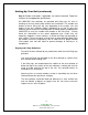
Normally Open Contacts Low Limit Receiver + - Low High Limit Com Limit - Optional Connection Using External Power Supply Supply Master Controller Input MUST NOT Be Connected TB4 Master Controller TB5 Alarm Relay Contacts Alarm Load (Internally Connected) TB1 L1 L2 Sol Com 1 2 3 4 Daisy Chain In Out + Supply TB3 Using DCT1000 24V Supply Receiver + - Alarm Man Dt Com Mode Ovr Cln Alarm Reset Com TB3 4-20 mA Connections Daisy Chain In Out 4-20 mA Connections Pressure High Limit Swit
when routing the air hoses to ensure that any potential condensation or moisture will not drain into the sensor. Where heavy condensation is present, a drip loop or an in-line filter should be installed to ensure long term operation. button on the control panel or by an external switch connected between the alarm-reset terminal and one of the common terminals. The alarm reset will only operate if the pressure module is installed and the pressure has returned to a normal condition. 2.
available. You will note that both the master controllers and slave boards have a telephone style connector mounted on the upper right hand side of the board. These connectors are for use in systems requiring slave boards that must be daisy chained together to provide additional channel capability. For systems that require the slave boards, the master controller must not have any connection made to its daisy chain input unless it is designated as a slave control itself.
3.6 High Alarm Setup The operation of the High Alarm Setup is identical to the High and Low Limit Setup and is only available when a pressure module is installed. The High Alarm default is 6.0″ w.c. [1.49 kPa]. The upper settable value is the calibration pressure of the pressure module and the lower limit is zero. Pressing Select will change the system to the Low Alarm Setup mode. 3.7 Low Alarm Setup The operation of the Low Alarm Setup is identical to the High and Low Limit Setup.
4.4 Error Codes 5.0 Glossary of Terms Error codes will be displayed on the three-digit display when certain faults occur. Most of these indicators are associated with the daisy chain communication, but certain error codes pertain to single board operation also. These codes are: • Run Mode: The term used when the timer board is firing the solenoids.
2-3/4 [69.85] HIGH LOW LIMIT COM LIMIT ALARM MAN DT ALARM COM MODE OVR CLN RESET COM PROCESS {IN 0} LAST OUTPUT TIME OFF (SEC) TIME ON (MSEC) HIGH LIMIT UP RUN ALARM RESET DOWN LOW LIMIT HIGH ALARM LOW ALARM CYCLE DELAY (MIN) MANUAL OVERRIDE SELECT DOWN TIME CYCLES (MIN) AUTO ALARM RESET (SEC) 6-1/4 [158.75] 6-7/8 [174.62] 8-1/4 [209.55] 1-13/16 [46.04] 8-3/4 [233.
Section 6- Troubleshooting 0 +95 .) ( ) %+. 55 0 Excessive Pressure Drop Across Filter Cartridges The differential pressure gauge or manometer on your dust collector should read 6” w.g. or less. Higher readings and/or steadily increasing readings are an indication that the main airflow through the dust collector may be restricted and a potential process problem such as poor suction at duct pickup points may exist. In extreme cases (over 17” w.g.) filter cartridges will be damaged.
0 +95 .) ( ) %+. 55 03 + 24 Filter Cartridges Loaded with Dust This is a condition known as blinding. If the dust is dry see the next four paragraphs below. If the dust is wet see the paragraphs below on “Water Leaks” and “Condensation”. Dust Not Discharging from the Hopper Check hopper for over-loading or bridging across the dust discharge. Correct by repairing dust discharge equipment, replacing with higher capacity equipment, installing hopper vibrators, etc. as required to keep the hopper empty.
0 +95 .) ( ) %+. 55 03 + 24 Condensation If moisture has been condensing inside the collector check the dew point temperature of the incoming air stream. It may be necessary to insulate the collector and/or the ductwork leading to the collector to keep surface temperatures above the dew point and prevent condensation inside the dust collector.
0 +95 .) ( ) %+. 55 03 + 24 Continuous Flow of Dust in the Clean Air Exhaust (Primary Dusting) Holes in the tube sheets Check the tube sheet for holes, cracks or loose bolts that would permit dusty air to bypass the filter cartridges. Puff of dust in the clean air exhaust after each pulse (Secondary Dusting) Compressed air manifold pressure too high Check compressed air manifold pressure gauge.
0 +95 .) ( ) %+. 55 03 + 24 Chemical attack Filter material degrades due to attack from certain chemicals in the dust or gasses in the air stream. High moisture High moisture content in the collector may cause certain filter cartridge material to shrink, degrade (more rapidly at elevated temperatures) or blind off. Localized abrasion Abrasion of the filter cartridges where high velocity dusty air hits the filter cartridges.
0 +95 .) ( ) - ,0 .. 2 0 7. - Pulsing failure of all valves or the same numbered valve on each header Pulse timer board inoperative Check pulse timer board for 120 VAC pulse between each numbered terminal on timer board and solenoid common terminal. Repair or replace timer if necessary. Open or short circuit in wiring between pulse timer board and solenoids Check continuity with ohmmeter or suitable tester and repair as required.
Section 7 – Routine Maintenance Inspection Frequency will vary as widely as there are operating conditions. general proceed as follows: In Daily – Check unit differential pressure. Weekly – Check pulse timer board and solenoid valves for function. This usually is only listening to verify uniform time in intervals between blasts. Monthly – Lubricate fan, rotary valve and screw conveyor. Check seals on latter two for dust loss.
Section 8 – Appendix Dust Collection Terms & Definitions Air-to-Cloth Ratio – Ratio of the volume of gas filtered (in ACFM) to the amount of filter media (in square feet). Cartridge Blinding – A condition where dust particles become embedded in the fabric over time and are not removed by the cleaning mechanism. This results in an increased pressure drop across the filter cartridge media. Bleed Through – Small particles of dust that are able to migrate through the filter cartridges.
Pressure Drop – Another term for differential pressure or the drop in pressure between two measured points. Re-Entrainment – The re-depositing of dust on the filter media after it has been cleaned off. This can be caused by turbulence in the hopper (or dirty air plenum) or by excessive airflow through the dust collector. Solenoid Valve – In the case of a dust collector, a solenoid valve is used to open and close a diaphragm valve.