REVERSE AIR - MODEL SWF DUST COLLECTOR BAGHOUSE (Fan Mounted Outside Unit) INSTRUCTION, OPERATIONS & MAINTENANCE MANUAL CAMCORP, INC.
TABLE OF CONTENTS OPERATING PRINCIPLE & SECTION/PARTS DETAIL........................................... 1-1 RECEIVING & INSPECTION OF UNIT....................................................................... 2-1 ON SITE STORAGE RECOMMENDATIONS ............................................................. 3-1 SETTING UP YOUR UNIT............................................................................................ 4-1 BAG & CAGE INSTALLATION ..........................................................
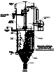
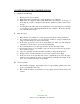
OPERATION PRINCIPLE A. Solids laden air or gases enter the unit at the hopper or housing inlet. B. Air passes through the filter media. C. Solids are retained on the filter media surface. D. Cleaning consists of a rotating sweep arm with nozzles positioned over the bags that continuously blows a reverse flow of air into the bags. 1. This momentarily takes a row of bags off stream through pressure reversal. 2. Flexing filter bags. 3.
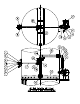
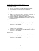
Camcorp Reverse Air Field Assembled Components Item Quantity Description 1 1 Motor, ½ HP or 1 HP - 1,800 RPM, 56C, 208-230/460/3/60 2 1 Primary Gear Reducer, 133Q56R20, 20:1 Ratio 3 1 Adapter Kit 4 1 Secondary Gear Reducer, 206Q56L40, 40:1 Ratio 5 1 Bracket Kit, 206S-BK (Secondary Reducer) 6 1 Motor Mounting Plate 7 2 Drive Mount Table Wall Brackets 8 1 Ball Bearing, 4-Bolt Flange, 1 ¼” 9 1 Chain Coupling 10 1 Reverse Air Fan (Size Determined by Unit Size) 11 1 Fan Inlet S
RECEIVING YOUR UNIT Prior to accepting shipment, care must be taken to inspect all equipment received both for proper count and for damage. Any and all irregularities must be noted on the carriers’ copy of the shipping receipt to assist in settling any claims for damage or shortages. All equipment is shipped FOB point of origin whether on a prepaid or collect freight basis. ANY CLAIM FOR DAMAGE IN TRANSIT OR SHORTAGES MUST BE BROUGHT AGAINST THE CARRIER BY THE PURCHASER.
ON SITE STORAGE RECOMMENDATIONS I. Baghouse and Housing 1. Housing can be stored outside. 2. Equipment must be blacked up to keep the flanges out of the dirt. 3. Many units are supplied with a plain finish bare steel interior. If storage of more than two week is anticipated, the interior should be prime coated before storage. 4. Covering the unit with a tarp is recommended to keep the interior from rusting or corroding as well as keeping the finish in new condition.
ON SITE STORAGE RECOMMENDATIONS (continued) IV. Fan and Fan Accessories 1. Fans can be stored outside on a pallet or skid to keep out of water and dirt. 2. Equipment should be covered with a tarp to protect from the bags. 3. Fan silencers, outlet dampers, and inlet boxes should also be tarped and stored on a pallet or skid. V. Ducting 1. Ducting can be stored outside on a pallet or skid to keep it off the ground. It should be positioned so that water does not sit in the equipment. 2.
ON SITE STORAGE RECOMMENDATIONS (continued) IX. Butterfly (Wafer Valve) 1. All limit switches, solenoids, and air cylinder ports must be capped and taped to prevent any moisture or dirt from entering. 2. Unit can be stored outside provided it is covered with a tarp and is on a pallet or skid to keep it out of the water and dirt and sunlight. X. Level Indicators Store these items inside a cool dry area protected from rodents XI.
SETTING UP YOUR UNIT CAMCORP dust collectors are shipped in various states of assembly depending on the size and configuration of the unit. Before attempting to move the dust collector or any of its sections, review both the certified general assembly drawing supplied with your unit and the rigging and lifting guidelines included in this manual.
Platform Installation: The platform, ladder, handrail, and bracing are to be installed as shown on the general arrangement drawing. Fan platforms are mounted onto bolt-on mounting gussets that attach to the sidewall. Explosion Vents (where applicable): 1. Figure 6 – The explosion vents are attached with a minimum of standard steel fasteners for shipment. THESE MUST BE REMOVED and the PVC Bolts installed that are included in the shipment.
TOP LOAD BAG AND CAGE INSTALLATION 1. Inspect the cage for any signs of damage, warping, bent wires, or missing welds. 2. Inspect the filter bag for any signs of mold, mildew, ripped seams, or holes. 3. Lower the closed end of the bag through the hole in the tube sheet. 4. With your hands, “kidney shape” the snap band bag top in order to fit and align it within the tube sheet hole. 5. Fit the groove of the snap band to the I.D. of the tube sheet hole and allow it to expand and audibly snap into place.
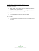
PRODUCT HIGHLIGHT Snapband BEADED SNAPBAND FILTER BAG DESIGN FOR FLAT TUBESHEET HOLE The snapband was developed to improve sealing efficiency. This design eliminates multiple parts, minimizing labor expenses. Camcorp provides a uniform double beaded gasket in the cuff assembly. This assures a leakproof seal for flat plate tubesheet holes. When installing the bags, follow instructions provided. PROPER INSTALLATION OF THE CUFF 1. Form the snapband into the shape of a kidney.
START-UP CHECKLIST 1. Installation Make sure the unit is secured to grade. The ladder(s) and platform(s) must be tightened and set up according to OSHA requirements. Ducting and piping must be secured and routed out of the way of traffic whenever possible to avoid injury. Ducting must also be free of all debris including moisture. 2. Interior of the dirty air plenum A. Make sure that the filter bag assemblies hang straight and the bottoms do not touch each other or any part of the collector interior.
START-UP DUST CONTROL SYSTEMS 1. Fan or blower system A. Start the fan or blower and check rotation. B. Check dust pickup points for proper suction; balance airflow in individual ducts. C. Check for air leakage at all flanged connections. 2. Equipment start-up sequence A. Start the sweep arm drive motor (direction of rotation is not critical). B. Start the reverse air fan motor and check rotation. C.
SHUT-DOWN PROCEDURES 1. Dust control systems Reverse start-up procedure, shut down fan, then after 5 or 10 minute delay, shut down the reverse air fan and sweep arm drive motor. 2. Pneumatic systems Reverse start-up procedure, shut down fan, then after 5 or 10 minute delay, shut down the reverse air fan and sweep arm drive motor. 8-1 CAMCORP, INC.
TROUBLESHOOTING THE DUST COLLECTOR I. Excessive pressure drop across filter bags The differential pressure gauge or manometer on your dust collector should read 6” w.g. or less. Higher readings and/or steadily increasing readings are an indication that the main airflow through the dust collector may be restricted, and a potential process problem such as poor suction at duct pickup points may exist. In extreme cases (over 17” w.g.) filter bags will be damaged. Check the following: A.
TROUBLESHOOTING THE DUST COLLECTOR (continued) Visually inspect the bags for heavy caking; if caking is evident, see the note below and take the necessary action to clean the bags. Next, measure the main airflow with a pitot tube or equivalent devise and compare with the original volume for which the unit was designed. If the flow is too high, cut back the main fan to prevent a recurrence of the problem. 3.
TROUBLESHOOTING THE DUST COLLECTOR (continued) II. Extremely Low Pressure Drop A. Pressure Gauge Check the differential pressure gauge or manometer and the tubing leading to the dust collector as in I-A of this section. B. Holes in Filter Bags or Bags Incorrectly Installed. Inspect the filter bags for holes, rips, tears, or excessive wear. Make sure that the filter bags were installed correctly according to the “Bag & Cage Installation” section. C.
TROUBLESHOOTING THE DUST COLLECTOR (continued) B. Residual Dust If dust has gotten into the clean air plenum because of a dropped or torn bag, hole in tube sheet, etc., the reverse air may stir up the dust and allow it to escape into the clean air exhaust. Residual dust may also be driven down inside the filter bags by the reverse air; if the filter bags are filled with several inches of dust, clean both the clean air plenum and the filter bags to avoid further problems. V.
TROUBLESHOOTING THE CLEANING MECHANISM 1. Fan - If the fan is not operating properly please refer to the New York Blower manual located in this IOM manual. 2. Sweep Arm Drive – Motor not rotating. A. Remove the motor from the gear drive and check for proper operation. If the motor does not rotate, repair or replace. B. If the motor does rotate properly check for binding or roughness in the gear drive. Repair or replace one or both gear boxes as necessary. 3.
SAFETY RECOMMENDATIONS Because this unit may be under pressure, do not attempt to open any device doors or panels while fans or blowers are running. If your unit is equipped with a discharge auger or an airlock, be sure chain guards are installed before start-up and servicing is attempted only after electrical power is locked out. While servicing the filter, it is very important that there are no open flames, welding or grinding sparks.
ROUTINE MAINTENANCE A. Inspection Frequency will vary as widely as there are operating conditions. In general proceed as follows: 1. Daily – Check unit differential pressure. 2. Weekly – Verify that the sweep arm drive and reverse air fan are operating properly. 3. Monthly – Lubricate fan, rotary valve and screw conveyor. Check seals on latter two for dust loss. 4. Quarterly – On Top Access Units, check for dust accumulation in clean air plenum. B. Repairs 1.
COMPONENT IOM MANUALS MORSE RAIDER WORM GEAR SPEED REDUCER (Maintenance)......................... 1-8 BROWNING BEVEL BOX ……………………………………………………………. 9 MARTIN TORQUE LIMITER CLUTCH ................................................................. 10-12 NEW YORK BLOWER PRESSURE BLOWER (IOM) ............................................
Emerson Power Transmission FORM P O Box 687 MAYSVILLE, KY 41056 Phone: 800-626-2093 www.emerson-ept.com 8721 March 2003 ® MAINTENANCE INSTRUCTIONS FOR WORM GEAR SPEED REDUCERS Center Distances 1.33, 1.54, 1.75, 2.06, 2.37, 2.62, 3.00, 3.25 3.75, 4.50, 5.16 and 6.
INTRODUCTION The following instructions apply to RAIDER® Worm Gear Speed Reducers. When ordering parts or requesting information be sure to provide all the data stamped on the reducer nameplate. EQUIPMENT REQUIRED In addition to standard Mechanic's tools, the following equipment is required: arbor press, wheel puller, torque wrench, dial indicator, seal driver, bluing, adhesive sealant, snap ring pliers for internal and external rings.
3. High speed shaft (worm shaft) removal: 1.33 C.D. through 3.25 C.D.: C-Flange units Use a small chisel to make a groove in the stamped steel cover opposite the motor flange. Pry off the cover. Remove internal snap ring from housing bore. Remove motor flange. Using a plastic hammer, gently tap on the motor end of the shaft to feed worm shaft assembly through housing and out. 3.75 C.D. through 6.00 C.D.: Remove motor flange. Remove seal cage opposite motor face. Keep shims with seal cage for reassembly.
D. Work seal loose. Be careful to keep all metal or dirt particles from entering unit. Remove old sealing compound from seal seat if it is present. Also remove burrs and sharp edges from shaft. Clean with rag moistened with solvent. Do not use abrasive material on shaft seal contacting surface. E. Protect seal lips when handling; seal leakage will result if these are damaged. If a seal with rubber coating on the outside diameter (O.D.) is used, no sealant is necessary. If no rubber coating is on seal O.D.
Lubricate Bearing Bores of Housing. Sub-assemble the rear bearing onto worm shaft. Lock rear bearing onto shaft with external snap ring. Insert shaft assembly from opposite extension end into housing until bearing is seated against shoulder in bore. Lock shaft assembly in housing bore with internal snap ring. Coat outside diameter of stamped steel endcover with adhesive sealant (except, if end cover is rubber coated DO NOT use sealant) and press into input bore opposite extension, until flush with housing.
4. Seals - To reassemble seals to unit, see Parts Service Steps on Page 3. 5. Motorized Coupling Adapter Reassemble using the original dimensions determined under "General Instructions" on Page 2. 6. Final Inspection A. Turn the gear train by hand as a final check. B. Re-install reducer and accessories. C. Fill reducer with the recommended oil to the appropriate level. See the installation instructions supplied with the reducer. D.
Emerson Power Transmission FORM P O Box 687 MAYSVILLE, KY 41056 Phone: 800-626-2093 www.emerson-ept.com 7893-E Revised May, 2002 RIGHT ANGLE BEVEL GEAR BOXES INSTALLATION & LUBRICATION INSTRUCTIONS ! WARNING Reducer shipped without oil. Fill to proper level before operating to avoid equipment damage and/or personal injury. Read and follow all instructions on this sheet. ! WARNING High voltage and rotating parts may cause serious or fatal injury. Turn off power to install or service.
Martin BULLETIN TL-1 SPROCKET & GEAR, INC.
Torque-Limiter Clutches Martin TORQUE-LIMITER Torque-Limiter clutches may be used with a sprocket, gear, sheave, flange or other driven member. It is recommended that the rubbing sides of the driven member be ground to provide a smooth rubbing surface of 65 to 125 micro-inches. See torque rating table on following page. clutch offers thrifty overload protection that’s easy to adjust.
Torque-Limiter Clutches TORQUE-LIMITER CLUTCHES Stock Plate Sprockets with Ground Each assembled unit contains one spring. Higher ratings can be obtained by ordering a second spring to nest in the original one. Bushings need to be ordered separately if required. G E Face and Bored to Fit the B E D C Torque Limiter J L K UNIT TT25 A The rubbing sides of the center member should be ground parallel — 65 to 125 micro-inches.
Coupling Safety WARNING & SAFETY REMINDER Safety must be considered a basic factor in machinery operation at all times. Most accidents are the result of carelessness or negligence. All rotating power transmission products are potentially dangerous and must be guarded by the contractor, installer, purchaser, owner, and user as required by applicable laws, regulations, standards, and good safety practice.
12345 INSTALLATION MAINTENANCE, OPERATING INSTRUCTIONS IM-140 PRESSURE BLOWERS TYPE HP PRESSURE BLOWERS SOUND THIS FAN HAS MOVING PARTS THAT CAN CAUSE SERIOUS BODILY INJURY. BEFORE OPERATING OR STARTING MAINTENANCE READ THE INSTALLATION AND MAINTENANCE INSTRUCTIONS AND THE AMCA SAFETY PRACTICES MANUAL PROVIDED WITH THIS FAN. DURING OPERATION 1. KEEP BODY, HANDS, AND FOREIGH OBJECTS AWAY FROM THE INLET, THE OUTLET, AND THE OTHER MOVING PARTS OF THE FAN SUCH AS SHAFTS, BELTS, AND PULLEYS. 2.
HANDLING AND STORAGE Fans should be lifted by the base, mounting supports, or lifting eyes only. Never lift a fan by the wheel, shaft, motor, motor bracket, housing inlet, outlet, or any fan part not designed for lifting. A spreader should always be used to avoid damage. On a direct drive Arrangement 8 fan, lifting holes are provided in the motor base to assist in handling the fan assembly.
3. Belts tend to stretch somewhat after installation. Recheck tension after several days of operation. Check sheave alignment as well as setscrew and/or bushing bolt tightness. COUPLING Coupling alignment should be checked after installation and prior to start up. Alignment is set at the factory, but shipping, handling, and installation can cause misalignment. Also check for proper coupling lubrication.
Table 1 - WHEEL SETSCREW TORQUES Setscrew Size Carbon Steel Setscrew Torque* Diameter (in.) lb.-in. lb.-ft. 1/2 5/8 3/4 600 --- 50 97 168 * Stainless Steel setscrews are not hardened and should not be tightened to more than 1/2 the values shown. Table 2 - BEARING SETSCREW TORQUE, lb.-in.
Lubrication Use the table for relubrication scheduling according to operating speed and shaft diameter. Bearings should be lubricated with a premium quality lithium-based grease conforming to NLGI Grade 2. Examples are: Mobil Texaco - Mobilith AW2 Premium RB Chevron Shell - Amolith #2 Alvania #2 These greases are for bearing surface temperatures of 40°F. to 180°F. For surface temperatures of 181°F. to 230°F. use Mobilith SHC220.
SPECIFY ROTATION AS VIEWED FROM DRIVE SIDE Parts List 1. 2. 3. 4. 5. 6. 7. Inlet Plate Assembly Wheel* Housing* Pedestal Assembly Motor Shaft Bearings * Order for parts must specify rotation. For assistance in selecting replacement parts, contact your local nyb representative or visit: http://www.nyb.com. Form 300 GPB 5M ABP Printed in U.S.A.
Preventative Maintenance Program Check Magnahelic gauge daily. This will provide a clear indication of any problem in the system. If gauge is not working repair or replace as soon as possible. External Gear Reducer Change initial oil after 500 hours or 5 weeks. Change oil every 2500 hours of service or 6 months. Bevel Box Gear Reducer (Inside Unit) Change initial oil after one week or 100 hours operation. Change oil every 2500 hours of service or 6 months.