CV-TAC400 Telephone Access System Installation Guide
Copyright Notice Copyright © 1995 – 2012 by Camden Door Controls Inc. All rights reserved Worldwide. Printed in Canada. This publication has been provided pursuant to an agreement containing restrictions on its use.
Table of Contents Hardware _________________________________________________ 8 Software ________________________________________________ 10 Installing the SFT5202 Software ______________________________ 10 1.On a Windows XP system, follow the steps below: ___________ 10 2.
CV-TAC400 Installation Guide | 4 7.Set the Time and Date _________________________________ 41 8.Set the DIP Address of the CV-TAC400 to 1 ________________ 43 9.Starting the SFT5202 Windows Client Software _____________ 43 10.
CV-TAC400 Installation Guide | 5 Changing/Adding Suite Information ___________________________ 87 18.PIN Entry Information _________________________________ 88 19.Backup the Data _____________________________________ 89 20.Uploading Saved Information into the CV-TAC400 __________ 90 Basic Master with Slave Unit and Access Control ________________ 92 Hardware Connections ______________________________________ 92 1.Connect the Telephone Line ____________________________ 92 2.
| 1 Product Overview The CV-TAC400 Entry Phone provides a simple, efficient and cost effective solution to condominium townhouse or gated community access control and suite monitoring. The base unit permits multiple devices for Door, Elevator and Garage control connected to its RS485 network. The directory lists multiple suites and provides access codes with access levels. The access and elevator levels determine what areas are accessible to the resident.
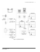
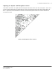
CV-TAC400 Installation Guide | 7 Figure 1 - System Block Diagram File: CV-TAC400_IN_MAN__NF_REV6.
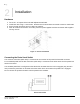
| 2 Installation Hardware 1. 2. 3. 4. Cut a 10” x 10” square hole in the wall adjacent to wall stud. Install back box using 3 - #10 screws. Wood screws for wood studs and metal screws for metal studs. Punch through knockouts and run cables as required. After all electrical connections are made, place front panel against back box and fasten with supplied security screws.
CV-TAC400 Installation Guide | 9 Adjusting the Speaker and Microphone Volume The volume controls for the speaker and the microphone are found on the rear of the front panel. There are 2 volume control potentiometers located at the top center of the main PCB as shown below marked SPKv and MICv.. Adjust the controls clockwise to increase the volume/microphone levels and counter clockwise to decrease the levels. Speaker and Microphone Volume Controls File: CV-TAC400_IN_MAN__NF_REV6.
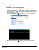
CV-TAC400 Installation Guide | 10 Software Installing the SFT5202 Software 1. On a Windows XP system, follow the steps below: a. Insert the CD into the computer. The system will open a dialog box allowing you to choose what to do with the CD. Choose the “Open Folder to View Files…” option. (if a window doesn’t automatically open use the Windows Explorer to view the files on the CD). b. Select the “db-inst.bat” file with the right mouse button. A menu will open up next to the file.
CV-TAC400 Installation Guide | 11 In that menu select the “Open” option. A command window will open and an installation screen will appear. Follow the directions on the screen. If a security screen appears allow the installation to proceed. d. When the installation is complete restart the system. 2. On a Windows Vista system, follow the steps below: a. Insert the CD into the computer. File: CV-TAC400_IN_MAN__NF_REV6.
CV-TAC400 Installation Guide | 12 The system will open a dialog box allowing you to choose what to do with the CD. Choose the “Open Folder to View Files…” option. (if a window doesn’t automatically open use the Windows Explorer to view the files on the CD) b. Select the “db-inst.bat” file with the right mouse button. A menu will open up next to the file. In that menu select the “Run as administrator” option. A command window will open, processes will run automatically and the command window will close.
CV-TAC400 Installation Guide | 13 In that menu select the “Open” option. A command window will open and an installation screen will appear. Follow the directions on the screen. If a security screen appears allow the installation to proceed. d. When the installation is complete restart the system. File: CV-TAC400_IN_MAN__NF_REV6.
| 3 Configurations CV-TAC400 integrated telephone entry and access control system is ideal for multi-unit residential and commercial buildings, with up to 500 suites/names. As a stand-alone telephone entry system, CV-TAC400 provides maximum performance, durability and economy. In a multi-panel (up to 3 slave panels), integrated configuration (telephone entry and card access) or with multiple locations, CV-TAC400 provides unprecedented performance and value.
| 3.1 Configurations Basic Master Configuration These instructions are for a CV-TAC400 configured as a master device to call suites over the telephone and allow entry through a single door when the correct telephone key is pressed. Hardware Connections All hardware connections are to be made before applying power to the unit. Using the Ferrite Cubes To maintain compliance with emission standards the installer must install the supplied Ferrite Cubes on the Power and Telephone line connections.
CV-TAC400 Installation Guide | 16 2. Connect the Modem Module (Optional) An optional CV-TAC4M modem module is used to connect to a remote computer for programming the CV-TAC400. The remote computer must have a modem connection and calls the CV-TAC400. Details of programming the CV-TAC400 are contained in the section “Remote Connection Using a Modem” When a modem connection is used the CV-TAC400 must be configured to use a shared phone line.
CV-TAC400 Installation Guide | 17 3. Connect the Computer If you are not using the modem module above, a direct connection to a computer is required for programming the CV-TAC400. An RS485 to USB converter is used. Connect the RS485 Converter as shown in Figure 5. Figure 5 - RS-485 Connection to Computer 4. Connect the Door Lock Connect the door lock to the door relay and door lock power. The exact nature of the connection depends on the specific lock used.
CV-TAC400 Installation Guide | 18 5. Connect the Power Connect power (12 VDC) to the CV-TAC400 power connections on Port 1. (Figure 7) Figure 7 - Door and Power Connections 6. Set the Time and Date Setting the time and date requires you to login to the CV-TAC400 locally via the front panel. A. Logging In To access the service mode the user must login with a password. To do this, follow the steps below: Press and hold the 1, 4 and 7 buttons until the display shows “Enter password [_ ]”.
CV-TAC400 Installation Guide | 19 If you enter the wrong password five times in a row, you will be locked out of the unit for 2Hrs. Even the help code will not be available. If the wrong password is entered the display will show: “Password Incorrect”. You may then repeat the process. From the main menu select 4. Date & Time The Date and Time menu allows changing the CV-TAC400’s date and time. When the Date and Time menu is selected a display similar to the example figure below will be displayed.
CV-TAC400 Installation Guide | 20 address from the table below. To save the address you have just entered, press the # key. To exit without changing the password enter the * key. There must be one and only one Master CV-TAC400. Each system may have up to 3 slave CVTAC400’s. The addresses must be unique within each system. Address 1 14 15 16 CV-TAC400 Operation CV-TAC400 Master CV-TAC400 Slave 1 CV-TAC400 Slave 2 CV-TAC400 Slave 3 8.
CV-TAC400 Installation Guide | 21 Configuring the SFTD5202 Software for the Modem Overview Each time the modem is used the modem must be initialized. Once the modem is initialized it may be used until the SFTD 5202 software is closed. Finding the COM Port To identify the modem to the SFTD5202 software the computer system gives it a name, such as COM3. To use the modem you must know its COM port number. Determining the COM port varies depending on the computer’s operating system.
CV-TAC400 Installation Guide | 22 f. g. h. i. j. k. l. In the “Com Port” drop down box, select the COM Port the Modem is connected to. In the “Data Bits” box select 8. In the “Flow Control” box select “none”. In the “Parity” box select “None”. In the “Stop Bits” box select “1”. In the “Echo” box select “”Off”. When you are done Save the settings by selecting the “Save Settings” button Initializing the Modem NOTE: The modem will remain initialized until the SFTD5202 software is shutdown.
CV-TAC400 Installation Guide | 23 c. The modem is initialized. Setting the Remote Modem Overview Each remote site that this system connects to will have an associated password and phone number. These may be stored in a list so that they may be easily accessed. Setting up a Remote Modem To add a remote site and its phone number and password to the list of sites follow the steps below: a. Start the SFT5202 Windows Client Software. b. Select the “Setup” menu. A list of submenus will be displayed c.
CV-TAC400 Installation Guide | 24 e. Enter the Remote telephone number in the “Telephone Number” box. f. Enter the Remote modem Password in the “ELP Default Password” box. g. Enter the Building Identification in the “Building Information” box. h. Select “OK” to save the information or “Close” to exit without saving Starting a Connection Overview To communicate with a remote system via modem you must first start the connection.
CV-TAC400 Installation Guide | 25 d. Select the “Dial Up” submenu. The “Dial Up” form will be displayed. e. Select the remote site from the list of remote sites in the “Building” drop down list. If the building is not in the list you may enter the information in the form. f. Select the “Dial up” button to start the connection or Close to exit with starting the connection. File: CV-TAC400_IN_MAN__NF_REV6.
CV-TAC400 Installation Guide | 26 RS485 to USB Converter Plug the USB to RS485 converter into an empty USB port on your computer. A prompt to search the internet for a driver will pop up. Select ‘No, not this time’ Press Next. In the next window, select ‘Install from a list or specific location [Advanced]’ Select ‘Include this location in the search’ and press Browse. In the Browse For Folder window, select the software CD supplied with your system. File: CV-TAC400_IN_MAN__NF_REV6.
CV-TAC400 Installation Guide | 27 Open the USBtoRS485_Drivers folder and select the CM20602 folder. Press OK. Select Next to start installing the driver. The driver will be installed. Select Finish when done. File: CV-TAC400_IN_MAN__NF_REV6.
CV-TAC400 Installation Guide | 28 10. Open a Session with the CV-TAC400 (Working Online with an RS485 Converter)) a. Select the Session Menu. b. Select Open Session. c. Select OK when the session has finished loading. 11. Open a Session with the CV-TAC400 (Working Online with a Modem Connection) a. Select the “File Setup/Maintenance” menu and select “Import Data from an CV-TAC400(s). File: CV-TAC400_IN_MAN__NF_REV6.
CV-TAC400 Installation Guide | 29 b. Scan for Remote CV-TAC400s. Select the remote CV-TAC400 from the list you wish to communicate with. c. The CV-TAC400’s data will be imported. The download from the remote CV-TAC400 can take up to 5 minutes. 12. Changing the Greeting Message To change the Greeting Message, perform the following steps: a) Select the “View/Edit Data Records” Menu. A list of submenus will be displayed. File: CV-TAC400_IN_MAN__NF_REV6.
CV-TAC400 Installation Guide | 30 b) Select the “Configuration Settings” submenu. The Configuration setting window will be displayed. Do not change the CV-TAC400 Address field at the top of the window. c) Select the “ELP Conf” tab. The ELP Configuration table will be displayed d) Open (Double click on) the “Greeting Message” field of the CV-TAC400 you wish to change. The field will open for editing. You may change the text as required.
CV-TAC400 Installation Guide | 31 b. Select the “Load the factory Default File into the computer” submenu. A file selection window will be displayed. c. Navigate the Explorer window to your CD Drive containing the installation CD. d. Select the ‘factory files’ folder. File: CV-TAC400_IN_MAN__NF_REV6.
CV-TAC400 Installation Guide | 32 e. Select the factory Default file -> 500DIrs(noname)-nouser and then select “Open” 14. Changing the Greeting Message To change the Greeting Message, perform the following steps: g) Select the “View/Edit Data Records” Menu. A list of submenus will be displayed. h) Select the “Configuration Settings” submenu. The Configuration setting window will be displayed. Do not change the CV-TAC400 Address field at the top of the window. i) Select the “ELP Conf” tab.
CV-TAC400 Installation Guide | 33 j) Open (Double click on) the “Greeting Message” field of the CV-TAC400 you wish to change. The field will open for editing. You may change the text as required. k) When the editing is complete press the “enter” key or select anywhere else in the “ELP Conf” table. l) Save and Upload the changed information. 15.
CV-TAC400 Installation Guide | 34 f. If required, Edit the Display Name in the “Display Name” field g. If required, Edit the Telephone Number in the “Telephone Num” field. h. When the editing for the selected suite is complete, select the “Save” button (on the bottom lefthand side of the form). i. When the editing for all the suites is complete, select the Close button(on the bottom right-hand side of the form) 16. PIN Entry Information The CV-TAC400 has a PIN entry function.
CV-TAC400 Installation Guide | 35 c. d. e. f. g. In the PIN Code edit box enter the new PIN code. In the Label edit box enter the associated Label Select the “Add” button. The PIN Code list grid will be updated. When all the changes have been completed, select the “SAVE” button. The data will be saved. Close the form by selecting the CLOSE button. 17. Backup the Data a. Select the Backup Menu b. Select Create Backup File: CV-TAC400_IN_MAN__NF_REV6.
CV-TAC400 Installation Guide | 36 c. Selection a location and create filename 18. Uploading Saved Information into the CV-TAC400 A. Working Online Using the RS485 Converter If you have been working online throughout this guide, all you need to do is close the session. a. Select the Session Menu b. Select Close Session. The new configuration data is automatically uploaded to the CVTAC400. File: CV-TAC400_IN_MAN__NF_REV6.
CV-TAC400 Installation Guide | 37 B. Working Online Using the Modem Module If you have been working online using the Modem Module, you cannot simply close the session. The new data must be exported to the CV-TAC400. a. Select the “Export Data to an ELP520(s)” from the “File Setup/Maintenance” menu. Select the ELP520 Address from the pull down menu and hit Export Now. b. The new configuration data is exported to the remote panel. File: CV-TAC400_IN_MAN__NF_REV6.
| 3.2 Configurations Master with Internal Access Control Reader These instructions are for a CV-TAC400 configured as a master device to call suites over the telephone and allows entry through a single door when the correct telephone key is pressed or the card proximity reader in the CV-TAC400 is used. Hardware Connections All hardware connections are to be made before applying power to the unit. 1. Connect the Telephone Line A dedicated telephone line is required.
CV-TAC400 Installation Guide | 39 The telephone line connected to the modem module may be the same telephone line used by the CVTAC400 to call the suites. Figure 9 - Optional Modem Module Connection 3. Connect the Computer If you are not using the modem module above, a direct connection to a computer is required for programming the CV-TAC400. An RS-485 to USB converter is used. Connect the Rs-485 Converter as shown in Figure 10. File: CV-TAC400_IN_MAN__NF_REV6.
CV-TAC400 Installation Guide | 40 Figure 10 - RS-485 Connection to Computer 4. Connect the Reader Installed in the CV-TAC400 Connect the reader installed in the CV-TAC400 to the connections in the CV-TAC400. The minimum connections are power, ground, D0 and D1. Figure 11 - Access Control Reader Connections 5. Connect the Door Lock Connect the door lock to the door relay and door lock power. The exact nature of the connection depends on the specific lock used. (Figure12) File: CV-TAC400_IN_MAN__NF_REV6.
CV-TAC400 Installation Guide | 41 Figure 12 - Door Strike Connection 6. Connect the Power Connect power (12 VDC) to the CV-TAC400 power connections on Port 1. (Figure 13) Figure 13 - Door and Power Connections 7. Set the Time and Date Setting the time and date requires you to login to the CV-TAC400 locally via the front panel. File: CV-TAC400_IN_MAN__NF_REV6.
CV-TAC400 Installation Guide | 42 A. Logging In To access the service mode for configuration the user must login with a password. To do this, follow the steps below: Press and hold the 1, 4 and 7 buttons until the display shows “Enter password [_ ]”. Enter the CV-TAC400’s password. The default Password is “1234#”. The Main Menu will be displayed. Main Menu 1. Event Log 2. Data Display 3. Service Menu 4. Date and Time 5.
CV-TAC400 Installation Guide | 43 8. Set the DIP Address of the CV-TAC400 to 1 From the front panel of the Master CV-TAC400, select 3 Service Menu from the Main Menu. Select 2 Change ELP Address. Service Menu 1. Change password 2. Change ELP Address 3. ELP Setup Menu 4. ELP Status Menu 5. Dispatch / Request Data 6. Restore ELP Default 7. Exit To change the CV-TAC400 DIP Address, enter the new address using the number keys. Select an address from the table below.
CV-TAC400 Installation Guide | 44 Remote Connection Using a Modem Overview The CV-TAC400 may be connected to a computer system over a telephone line. To do this the CVTAC400 requires the modem module. The computer requires a modem connected to it and the SFTD5202 software. Using the modem is identical to the RS485 connection after the connection has been made. Because a computer with a modem may be used to manage multiple CV-TAC400’s, the “Open Session” initialization is not used.
CV-TAC400 Installation Guide | 45 e. In “Connection” box select Modem. f. g. h. i. j. k. l. In the “Com Port” drop down box, select the COM Port the Modem is connected to. In the “Data Bits” box select 8. In the “Flow Control” box select “none”. In the “Parity” box select “None”. In the “Stop Bits” box select “1”. In the “Echo” box select “”Off”.
CV-TAC400 Installation Guide | 46 b. Select the “Save” button. c. The modem is initialized. Setting the Remote Modem Overview Each remote site that this system connects to will have an associated password and phone number. These may be stored in a list so that they may be easily accessed. Setting up a Remote Modem To add a remote site and its phone number and password to the list of sites follow the steps below: a. Start the SFT5202 Windows Client Software. b. Select the “Setup” menu.
CV-TAC400 Installation Guide | 47 d. Select the “Add” button. The “Modem Information” form will be displayed e. Enter the Remote telephone number in the “Telephone Number” box. f. Enter the Remote modem Password in the “ELP Default Password” box. g. Enter the Building Identification in the “Building Information” box. h. Select “OK” to save the information or “Close” to exit without saving Starting a Connection Overview File: CV-TAC400_IN_MAN__NF_REV6.
CV-TAC400 Installation Guide | 48 To communicate with a remote system via modem you must first start the connection. As the system does not know which system will be connected you do not use start session. Starting the Connection a. To start a connection to a remote system follow the steps below: b. Start the SFT5202 Windows Client Software. c. Select the “Setup” menu. A list of submenus will be displayed d. Select the “Dial Up” submenu. The “Dial Up” form will be displayed. e.
CV-TAC400 Installation Guide | 49 RS485 to USB Converter Plug the USB to RS485 converter into an empty USB port on your computer. A prompt to search the internet for a driver will pop up. Select ‘No, not this time’ Press Next. In the next window, select ‘Install from a list or specific location [Advanced]’ Select ‘Include this location in the search’ and press Browse. In the Browse For Folder window, select the software CD supplied with your system. File: CV-TAC400_IN_MAN__NF_REV6.
CV-TAC400 Installation Guide | 50 Open the USBtoRS485_Drivers folder and select the CM20602 folder. Press OK. Select Next to start installing the driver. The driver will be installed. Select Finish when done. File: CV-TAC400_IN_MAN__NF_REV6.
CV-TAC400 Installation Guide | 51 11. Open a Session with the CV-TAC400 (Working Online with an RS485 Converter)) a. Select the Session Menu. b. Select Open Session. c. Select OK when the session has finished loading. 12. Open a Session with the CV-TAC400 (Working Online with a Modem Connection) a. Select the “File Setup/Maintenance” menu and select “Import Data from an CV-TAC400(s). File: CV-TAC400_IN_MAN__NF_REV6.
CV-TAC400 Installation Guide | 52 b. Scan for Remote CV-TAC400s. Select the remote CV-TAC400 from the list you wish to communicate with. c. The CV-TAC400’s data will be imported. The download from the remote CV-TAC400 can take up to 5 minutes. 13. Changing the Greeting Message To change the Greeting Message, perform the following steps: a) Select the “View/Edit Data Records” Menu. A list of submenus will be displayed. File: CV-TAC400_IN_MAN__NF_REV6.
CV-TAC400 Installation Guide | 53 b) Select the “Configuration Settings” submenu. The Configuration setting window will be displayed. Do not change the CV-TAC400 Address field at the top of the window. c) Select the “ELP Conf” tab. The ELP Configuration table will be displayed d) Open (Double click on) the “Greeting Message” field of the CV-TAC400 you wish to change. The field will open for editing. You may change the text as required.
CV-TAC400 Installation Guide | 54 b. Select the “Load the factory Default File into the computer” submenu. A file selection window will be displayed. c. Navigate the Explorer window to your CD Drive containing the installation CD. d. Select the ‘factory files’ folder. File: CV-TAC400_IN_MAN__NF_REV6.
CV-TAC400 Installation Guide | 55 e. Select the factory Default file -> 500DIrs(noname)-nouser and then select “Open” File: CV-TAC400_IN_MAN__NF_REV6.
CV-TAC400 Installation Guide | 56 15. Set the Facility Code The CV-TAC400 is pre-programmed with Camden facility codes. The facility code does not need to be set if Camden proximity cards are used. To add or change a facility code, follow the steps below: a. Select the “View/Edit Data Records” Menu. A list of submenus will be displayed b. Select the “Configuration Settings” submenu. The Configuration setting window will be displayed. Do not change the CV-TAC400 Address field at the top of the window. c.
CV-TAC400 Installation Guide | 57 16. Setup the Access Control Information A. Default Settings To assist you in configuring the CV-TAC400 the factory default file is set up with some useful default settings. Time Group 1 is set to allow access 24 hours per day 7 days per week holidays included. Access Group 1 is doors number 1 though 8. Access Level 1 is the combination of Time Group 1 and Access Group 1.
CV-TAC400 Installation Guide | 58 c. Select the Access Level tab. The Access tables will be displayed. d. In the Access Group table select (double click) the Door ID entry you wish to edit. e. Enter the Door Id information and then press “Enter” f. When the editing for the selected Access Group is complete, select the “Save” button (on the bottom left-hand side of the form). C.
CV-TAC400 Installation Guide | 59 c. Select the Misc tab. The miscellaneous tables will be displayed. d. In the Time Group table select (double click) the Start Time entry you wish to edit. e. Enter the Start Time and then press “Enter” f. In the Time Group table select (double click) the End Time entry you wish to edit. Note: The End Time is inclusive, that is, the End Time itself is included in the time group g. Enter the End Time and then press “Enter” h.
CV-TAC400 Installation Guide | 60 c. Select the Access Level tab. The Access tables will be displayed. d. In the Access Level table select (double click) the Access Group ID entry you wish to edit. e. Enter the Access Group ID information and then press “Enter” f. In the Access Level table select (double click) the Time Group ID entry you wish to edit. g. Enter the Time Group Id information and then press “Enter” File: CV-TAC400_IN_MAN__NF_REV6.
CV-TAC400 Installation Guide | 61 h. When the editing for the selected Access Level is complete, select the “Save” button (on the bottom left-hand side of the form). 17. Entering Suite Information Changing/Adding Suite Information Floor, Express Code, Display Name, Telephone Number Note: All the Suite records are already in the factory default file. The information has been set to blank. To add a suite merely select a blank record and enter the information. j. Select the “View/Edit Data Records” Menu.
CV-TAC400 Installation Guide | 62 18. Configuring Users for Access Control Configuring a user means entering the numeric codes of the user’s keyfob/card and/or transmitter and assigning the user an Access Level. Each user may also be set as a “super” user. A. Adding a New User To add a new user follow the steps below: a. Select the “View/Edit Data Records” Menu. A list of submenus will be displayed b. Select the “Suite/Directory” submenu. The Suite/Directory Data window will be displayed. c.
CV-TAC400 Installation Guide | 63 Note: If the user does not reside in a suite, for example a cleaner, select a Suite ID that is not used for an actual suite. If this unused suite has a blank “Display Name” it will not show up in the directory. d. Select the “Add User” button. The “Add New User” form will be displayed. e. Enter the user information as required. Note: A User Name must always be entered so that the user may be listed in the reporting system. f. Click the “Save” button when completed.
CV-TAC400 Installation Guide | 64 19. PIN Entry Information The CV-TAC400 has a PIN entry function. When a user enters their assigned PIN (personal identification number) the CV-TAC400 grants access in the same way as if the number 6 was entered on a call to the suite. The CV-TAC400 maintains a list of PIN numbers and the associated Labels for the PIN. Each PIN number must be between 5 and 9 digits long.
CV-TAC400 Installation Guide | 65 20. Backup the Data a. Select the Backup Menu b. Select Create Backup c. Selection a location and create filename File: CV-TAC400_IN_MAN__NF_REV6.
CV-TAC400 Installation Guide | 66 21. Uploading Saved Information into the CV-TAC400 A. Working Online Using the Rs485 Converter If you have been working online throughout this guide, all you need to do is close the session. a. Select the Session Menu b. Select Close Session. The new configuration data is automatically uploaded to the CVTAC400. B. Working Online Using the Modem Module If you have been working online using the Modem Module, you cannot simply close the session.
CV-TAC400 Installation Guide | 67 b. The new configuration data is exported to the remote panel. File: CV-TAC400_IN_MAN__NF_REV6.
| 3.4 Configurations Basic Master with Slave Unit These instructions are for a CV-TAC400 configured as a master device to call suites over the telephone and allow entry through a single door when the correct telephone key is pressed. Hardware Connections All hardware connections are to be made before applying power to the unit. 1. Connect the Telephone Line A dedicated telephone line is required. TIP and RING connections are provided to allow connection to a telephone line.
CV-TAC400 Installation Guide | 69 Figure 15 - Optional Modem Module Connection 3. Connect the Computer If you are not using the modem module above, a direct connection to a computer is required for programming the CV-TAC400. An RS-485 to USB converter is used. Connect the Rs-485 Converter as shown in Figure 16. Figure 16 - RS-485 Connection to Computer File: CV-TAC400_IN_MAN__NF_REV6.
CV-TAC400 Installation Guide | 70 4. Connect the Door Lock Connect the door lock to the door relay and door lock power. The exact nature of the connection depends on the specific lock used. (Figure17) Figure 17 - Door Strike Connection 5. Connect the Slave Connect the Slaves RS485 bus (A1B1) to the Masters RS485 bus (A1B1). Figure 18 - Slave to Master Connections File: CV-TAC400_IN_MAN__NF_REV6.
CV-TAC400 Installation Guide | 71 6. Connect the Power Connect power (12 VDC) to the CV-TAC400 power connections on Port 1. (Figure 19) Figure 19 - Door and Power Connections 7. Set the Time and Date Setting the time and date requires you to login to the CV-TAC400 locally via the front panel. A. Logging In To access the service mode for configuration the user must login with a password.
CV-TAC400 Installation Guide | 72 From the main menu select 4:. Date & Time The Date and Time menu allows changing the CV-TAC400’s date and time. When the Date and Time menu is selected, a display similar to the example figure below will be displayed. ELP Time and Date: 2009–Oct-19 Monday 16:14:16 To change the date or time, you position the cursor under the item you want to change and then use the 1 and 3 keys to increment or decrement that item.
CV-TAC400 Installation Guide | 73 Address 1 14 15 16 CV-TAC400 Operation CV-TAC400 Master CV-TAC400 Slave 1 CV-TAC400 Slave 2 CV-TAC400 Slave 3 9. Set the DIP Address of the Slave CV-TAC400 From the front panel of the Slave CV-TAC400, select 3: Service Menu from the Main Menu. Select 2: Change ELP Address. Service Menu 1. Change password 2. Change ELP Address 3. ELP Setup Menu 4. ELP Status Menu 5. Dispatch / Request Data 6. Restore ELP Default 7.
CV-TAC400 Installation Guide | 74 11. Establishing a Connection with the CV-TAC400 The CV-TAC400 is programmed via a Windows PC, using an USB to RS485 converter for local access or an optional CV-TAC4M Modem Module for a remote dialup connection. Remote Connection Using a Modem Overview The CV-TAC400 may be connected to a computer system over a telephone line. To do this the CVTAC400 requires the modem module. The computer requires a modem connected to it and the SFTD5202 software.
CV-TAC400 Installation Guide | 75 e. In “Connection” box select Modem. f. g. h. i. j. k. l. In the “Com Port” drop down box, select the COM Port the Modem is connected to. In the “Data Bits” box select 8. In the “Flow Control” box select “none”. In the “Parity” box select “None”. In the “Stop Bits” box select “1”. In the “Echo” box select “”Off”.
CV-TAC400 Installation Guide | 76 b. Select the “Save” button. c. The modem is initialized. Setting the Remote Modem Overview Each remote site that this system connects to will have an associated password and phone number. These may be stored in a list so that they may be easily accessed. Setting up a Remote Modem To add a remote site and its phone number and password to the list of sites follow the steps below: a. Start the SFT5202 Windows Client Software. b. Select the “Setup” menu.
CV-TAC400 Installation Guide | 77 d. Select the “Add” button. The “Modem Information” form will be displayed e. Enter the Remote telephone number in the “Telephone Number” box. f. Enter the Remote modem Password in the “ELP Default Password” box. g. Enter the Building Identification in the “Building Information” box. h. Select “OK” to save the information or “Close” to exit without saving Starting a Connection Overview File: CV-TAC400_IN_MAN__NF_REV6.
CV-TAC400 Installation Guide | 78 To communicate with a remote system via modem you must first start the connection. As the system does not know which system will be connected you do not use start session. Starting the Connection a. To start a connection to a remote system follow the steps below: b. Start the SFT5202 Windows Client Software. c. Select the “Setup” menu. A list of submenus will be displayed d. Select the “Dial Up” submenu. The “Dial Up” form will be displayed. e.
CV-TAC400 Installation Guide | 79 RS485 to USB Converter Plug the USB to RS485 converter into an empty USB port on your computer. A prompt to search the internet for a driver will pop up. Select ‘No, not this time’ Press Next. In the next window, select ‘Install from a list or specific location [Advanced]’ Select ‘Include this location in the search’ and press Browse. In the Browse For Folder window, select the software CD supplied with your system. File: CV-TAC400_IN_MAN__NF_REV6.
CV-TAC400 Installation Guide | 80 Open the USBtoRS485_Drivers folder and select the CM20602 folder. Press OK. Select Next to start installing the driver. The driver will be installed. Select Finish when done. File: CV-TAC400_IN_MAN__NF_REV6.
CV-TAC400 Installation Guide | 81 12. Open a Session with the CV-TAC400 (Working Online with an RS485 Converter)) a. Select the Session Menu. b. Select Open Session. c. Select OK when the session has finished loading. 13. Open a Session with the CV-TAC400 (Working Online with a Modem Connection) a. Select the “File Setup/Maintenance” menu and select “Import Data from an CV-TAC400(s). File: CV-TAC400_IN_MAN__NF_REV6.
CV-TAC400 Installation Guide | 82 b. Scan for Remote CV-TAC400s. Select the remote CV-TAC400 from the list you wish to communicate with. c. The CV-TAC400’s data will be imported. The download from the remote CV-TAC400 can take up to 5 minutes. 14. Changing the Greeting Message To change the Greeting Message, perform the following steps: a) Select the “View/Edit Data Records” Menu. A list of submenus will be displayed. File: CV-TAC400_IN_MAN__NF_REV6.
CV-TAC400 Installation Guide | 83 b) Select the “Configuration Settings” submenu. The Configuration setting window will be displayed. Do not change the CV-TAC400 Address field at the top of the window. c) Select the “ELP Conf” tab. The ELP Configuration table will be displayed d) Open (Double click on) the “Greeting Message” field of the CV-TAC400 you wish to change. The field will open for editing. You may change the text as required.
CV-TAC400 Installation Guide | 84 b. Select the “Load the factory Default File into the computer” submenu. A file selection window will be displayed. c. Navigate the Explorer window to your CD Drive containing the installation CD. d. Select the ‘factory files’ folder. File: CV-TAC400_IN_MAN__NF_REV6.
CV-TAC400 Installation Guide | 85 e. Select the factory Default file -> 500DIrs(noname)-nouser and then select “Open” File: CV-TAC400_IN_MAN__NF_REV6.
CV-TAC400 Installation Guide | 86 16. Setup the CV-TAC400’s Configuration to Allow Slaves If the Master and Slave unit are to share a telephone line, telephone line sharing must be enabled. To turn on telephone line sharing, follow the steps below: a. Select the “View/Edit Data Records” Menu. A drop down menu box will be displayed. b. In the drop down menu select the “Configuration Settings” Submenu. The Configuration setting window will be displayed.
CV-TAC400 Installation Guide | 87 17. Entering Suite Information Changing/Adding Suite Information Floor, Express Code, Display Name, Telephone Number Note: All the Suite records are already in the factory default file. The information has been set to blank. To add a suite merely select a blank record and enter the information. a. Select the “View/Edit Data Records” Menu. A list of submenus will be displayed b. Select the “Suite/Directory Data” submenu. The Suite/Directory Data window will be displayed.
CV-TAC400 Installation Guide | 88 18. PIN Entry Information The CV-TAC400 has a PIN entry function. When a user enters their assigned PIN (personal identification number) the CV-TAC400 grants access in the same way as if the number 6 was entered on a call to the suite. The CV-TAC400 maintains a list of PIN numbers and the associated Labels for the PIN. Each PIN number must be between 5 and 9 digits long.
CV-TAC400 Installation Guide | 89 19. Backup the Data a. Select the Backup Menu b. Select Create Backup c. Selection a location and create filename File: CV-TAC400_IN_MAN__NF_REV6.
CV-TAC400 Installation Guide | 90 20. Uploading Saved Information into the CV-TAC400 A. Working Online Using the RS485 Converter If you have been working online throughout this guide, all you need to do is close the session. a. Select the Session Menu b. Select Close Session. The new configuration data is automatically uploaded to the CVTAC400. B. Working Online Using the Modem Module If you have been working online using the Modem Module, you cannot simply close the session.
CV-TAC400 Installation Guide | 91 b. The new configuration data is exported to the remote panel. File: CV-TAC400_IN_MAN__NF_REV6.
| 3.4 Configurations Basic Master with Slave Unit and Access Control These instructions are for a CV-TAC400 configured as a master device to call suites over the telephone and allow entry through a single door when the correct telephone key is pressed. A slave CV-TAC400 allows users entry through the door associated with the slave. Card readers in the CV-TAC400’s allow users to use cards or keyfobs to control entry through doors.
CV-TAC400 Installation Guide | 93 Figure 21 - Optional Modem Module Connection 3. Connect the Computer If you are not using the modem module above, a direct connection to a computer is required for programming the CV-TAC400. An RS-485 to USB converter is used. Connect the Rs-485 Converter as shown in Figure 22 Figure 22 - RS-485 Connection to Computer File: CV-TAC400_IN_MAN__NF_REV6.
CV-TAC400 Installation Guide | 94 4. Connect the Reader Installed in the CV-TAC400 Connect the reader installed in the CV-TAC400 to the connections in the CV-TAC400. The minimum connections are power, ground, D0 and D1. Figure 23 - Access Control Reader Connections 5. Connect the Slave Connect the Slaves RS485 bus (A1B1) to the Masters RS485 bus (A1B1). Figure 24 - Slave to Master Connections File: CV-TAC400_IN_MAN__NF_REV6.
CV-TAC400 Installation Guide | 95 6. Connect the Door Lock Connect the door lock to the door relay and door lock power. The exact nature of the connection depends on the specific lock used. Figure 25 - Door Strike Connection 7. Connect the Power Connect power (12 VDC) to the CV-TAC400 power connections on Port 1. (Figure 26) File: CV-TAC400_IN_MAN__NF_REV6.
CV-TAC400 Installation Guide | 96 Figure 26 - Door and Power Connections 8. Set the Time and Date Setting the time and date requires you to login to the CV-TAC400 locally via the front panel. A. Logging In To access the service mode for configuration the user must login with a password. To do this, follow the steps below: Press and hold the 1, 4 and 7 buttons until the display shows “Enter password [_ ]”. Enter the CV-TAC400’s password. The default Password is “1234#”. The Main Menu will be displayed.
CV-TAC400 Installation Guide | 97 The Date and Time menu allows changing the CV-TAC400’s date and time. When the Date and Time menu is selected a display similar to the example figure below will be displayed. ELP Time and Date: 2009–Oct-19 Monday 16:14:16 To change the date or time you position the cursor under the item you want to change and then use the 1 and 3 keys to increment or decrement that item. The # key moves the cursor right, and at the end of the line moves down to the next line.
CV-TAC400 Installation Guide | 98 Address 15 16 CV-TAC400 Operation CV-TAC400 Slave 2 CV-TAC400 Slave 3 10. Set the DIP Address of the Slave CV-TAC400 From the front panel of the Slave CV-TAC400, select 3 Service Menu from the Main Menu. Select 2 Change ELP Address. Service Menu 1. Change password 2. Change ELP Address 3. ELP Setup Menu 4. ELP Status Menu 5. Dispatch / Request Data 6. Restore ELP Default 7. Exit To change the CV-TAC400 DIP Address, enter the new address using the number keys.
CV-TAC400 Installation Guide | 99 12. Establishing a Connection with the CV-TAC400 The CV-TAC400 is programmed via a Windows PC, using an USB to RS485 converter for local access or an optional CV-TAC4M Modem Module for a remote dialup connection. Remote Connection Using a Modem Overview The CV-TAC400 may be connected to a computer system over a telephone line. To do this the CVTAC400 requires the modem module. The computer requires a modem connected to it and the SFTD5202 software.
CV-TAC400 Installation Guide | 100 e. In “Connection” box select Modem. f. g. h. i. j. k. l. In the “Com Port” drop down box, select the COM Port the Modem is connected to. In the “Data Bits” box select 8. In the “Flow Control” box select “none”. In the “Parity” box select “None”. In the “Stop Bits” box select “1”. In the “Echo” box select “”Off”.
CV-TAC400 Installation Guide | 101 b. Select the “Save” button. c. The modem is initialized. Setting the Remote Modem Overview Each remote site that this system connects to will have an associated password and phone number. These may be stored in a list so that they may be easily accessed. Setting up a Remote Modem To add a remote site and its phone number and password to the list of sites follow the steps below: a. Start the SFT5202 Windows Client Software. b. Select the “Setup” menu.
CV-TAC400 Installation Guide | 102 d. Select the “Add” button. The “Modem Information” form will be displayed e. Enter the Remote telephone number in the “Telephone Number” box. f. Enter the Remote modem Password in the “ELP Default Password” box. g. Enter the Building Identification in the “Building Information” box. h. Select “OK” to save the information or “Close” to exit without saving Starting a Connection Overview File: CV-TAC400_IN_MAN__NF_REV6.
CV-TAC400 Installation Guide | 103 To communicate with a remote system via modem you must first start the connection. As the system does not know which system will be connected you do not use start session. Starting the Connection a. To start a connection to a remote system follow the steps below: b. Start the SFT5202 Windows Client Software. c. Select the “Setup” menu. A list of submenus will be displayed d. Select the “Dial Up” submenu. The “Dial Up” form will be displayed. e.
CV-TAC400 Installation Guide | 104 A. RS485 to USB Converter Plug the USB to RS485 converter into an empty USB port on your computer. A prompt to search the internet for a driver will pop up. Select ‘No, not this time’ Press Next. In the next window, select ‘Install from a list or specific location [Advanced]’ Select ‘Include this location in the search’ and press Browse. In the Browse For Folder window, select the software CD supplied with your system. File: CV-TAC400_IN_MAN__NF_REV6.
CV-TAC400 Installation Guide | 105 Open the USBtoRS485_Drivers folder and select the CM20602 folder. Press OK. Select Next to start installing the driver. The driver will be installed. Select Finish when done. File: CV-TAC400_IN_MAN__NF_REV6.
CV-TAC400 Installation Guide | 106 13. Open a Session with the CV-TAC400 (Working Online with an RS485 Converter)) a. Select the Session Menu. b. Select Open Session. c. Select OK when the session has finished loading. 14. Open a Session with the CV-TAC400 (Working Online with a Modem Connection) a. Select the “File Setup/Maintenance” menu and select “Import Data from an CV-TAC400(s). File: CV-TAC400_IN_MAN__NF_REV6.
CV-TAC400 Installation Guide | 107 b. Scan for Remote CV-TAC400s. Select the remote CV-TAC400 from the list you wish to communicate with. c. The CV-TAC400’s data will be imported. The download from the remote CV-TAC400 can take up to 5 minutes. 15. Changing the Greeting Message To change the Greeting Message, perform the following steps: a) Select the “View/Edit Data Records” Menu. A list of submenus will be displayed. File: CV-TAC400_IN_MAN__NF_REV6.
CV-TAC400 Installation Guide | 108 b) Select the “Configuration Settings” submenu. The Configuration setting window will be displayed. Do not change the CV-TAC400 Address field at the top of the window. c) Select the “ELP Conf” tab. The ELP Configuration table will be displayed d) Open (Double click on) the “Greeting Message” field of the CV-TAC400 you wish to change. The field will open for editing. You may change the text as required.
CV-TAC400 Installation Guide | 109 b. Select the “Load the factory Default File into the computer” submenu. A file selection window will be displayed. c. Navigate the Explorer window to your CD Drive containing the installation CD. d. Select the ‘factory files’ folder. File: CV-TAC400_IN_MAN__NF_REV6.
CV-TAC400 Installation Guide | 110 e. Select the factory Default file -> 500DIrs(noname)-nouser and then select “Open” 17. Setup the CV-TAC400’s Configuration to Allow Slaves If the Master and Slave unit are to share a telephone line, telephone line sharing must be enables. To turn on telephone line sharing, follow the steps below: a. Select the “View/Edit Data Records” Menu. A drop down menu box will be displayed. b. In the drop down menu select the “Configuration Settings” Submenu.
CV-TAC400 Installation Guide | 111 c. Select the “ELP Conf” tab. TheCV-TAC400 Configuration tables will be displayed. d. For the first CV-TAC400 select the Option entry by double clicking e. In the Option entry enter “013” to add or “006” to delete Telephone line sharing followed by enter. Note Turning on telephone line sharing is done by adding 7 to the value in the Option entry. As the default value is 6, adding 7 gives 13. More detailed information is below. f.
CV-TAC400 Installation Guide | 112 c. Select the Misc tab. The miscellaneous tables will be displayed. d. In the Facility Code table select (double click) the Facility Code entry you wish to edit. e. Enter the Facility Code and then press “Enter” Note: Adding a Facility code is done by replacing one of the “0” entries with the Facility Code you wish to add. Zero is not a valid facility code f. When all the entries have been competed, select the Save button. g. To close the Form select the Close button. h.
CV-TAC400 Installation Guide | 113 What this means is that to allow a user to always pass through door 1, 2, 3, 4, 5, 6, 7, or 8, that user should be set to Access Level 1. The facility codes 34, 910 and 912 are already entered as factory default settings. Note: Access level 1 allows 24 hour access through doors 1 through 8 (unless modified by the installer). B. Configuring Access Groups Configuring an Access Group means adding a particular door to the group. The doors are identified by a Door ID number.
CV-TAC400 Installation Guide | 114 e. Enter the Door Id information and then press “Enter” f. When the editing for the selected Access Group is complete, select the “Save” button (on the bottom left-hand side of the form). C. Configuring Time Groups Configuring a Time Group means setting a start time, an end time and list of days of the week the time group is active. This is done in the Time Group List table. To Configure a Time Group follow the steps below: a. Select the “View/Edit Data Records” Menu.
CV-TAC400 Installation Guide | 115 e. Enter the Start Time and then press “Enter” f. In the Time Group table select (double click) the End Time entry you wish to edit. Note: The End Time is inclusive, that is, the End Time itself is included in the time group g. Enter the End Time and then press “Enter” h. Select “Y” in column for a day to include it “N” to exclude it. All Holidays may be included or excluded by setting the HOL column. i.
CV-TAC400 Installation Guide | 116 d. In the Access Level table select (double click) the Access Group ID entry you wish to edit. e. Enter the Access Group ID information and then press “Enter” f. In the Access Level table select (double click) the Time Group ID entry you wish to edit. g. Enter the Time Group Id information and then press “Enter” h. When the editing for the selected Access Level is complete, select the “Save” button (on the bottom left-hand side of the form).
CV-TAC400 Installation Guide | 117 20. Entering Suite Information Changing/Adding Suite Information Floor, Express Code, Display Name, Telephone Number Note: All the Suite records are already in the factory default file. The information has been set to blank. To add a suite merely select a blank record and enter the information. a. Select the “View/Edit Data Records” Menu. A list of submenus will be displayed. b. Select the “Suite/Directory Data” submenu. The Suite/Directory Data window will be displayed.
CV-TAC400 Installation Guide | 118 15, Configuring Users for Access Control Configuring a user means entering the numeric codes of the user’s keyfob/card and/or transmitter and assigning the user an Access Level. A. Adding a New User To add a new user follow the steps below: a. Select the “View/Edit Data Records” Menu. A list of submenus will be displayed b. Select the “Suite/Directory” submenu. The Suite/Directory Data window will be displayed. c.
CV-TAC400 Installation Guide | 119 e. Enter the user information as required. Note: A User Name must always be entered so that the user may be listed in the reporting system. f. Click the “Save” button when completed. The “Suite/Directory Data” form is displayed. Note: The close button closes the form and discards any changes. g. Click the “Save” button. h. When you have completed all the User Access changes click the “Close” button. 21. PIN Entry Information The CV-TAC400 has a PIN entry function.
CV-TAC400 Installation Guide | 120 A. Configuring PIN Codes To configure the PIN codes follow the steps below: i. Adding a New PIN Code a. Select the “View/Edit Data Records” Menu. A drop down menu box will be displayed. b. In the drop down menu select the “PIN Code” Submenu. The PIN Code form will be displayed. c. d. e. f. g. In the PIN Code edit box, enter the new PIN code. In the Label edit box, enter the associated Label Select the “Add” button. The PIN Code list grid will be updated.
CV-TAC400 Installation Guide | 121 b. Select Create Backup c. Selection a location and create filename 23. Uploading Saved Information into the CV-TAC400 A. Working Online If you have been working online throughout this guide, all you need to do is close the session. a. Select the Session Menu File: CV-TAC400_IN_MAN__NF_REV6.
CV-TAC400 Installation Guide | 122 b. Select Close Session. The new configuration data is automatically uploaded to the CVTAC400. B. Working Online Using the Modem Module If you have been working online using the Modem Module, you cannot simply close the session. The new data must be exported to the CV-TAC400. a. Select the “Export Data to an ELP520(s)” from the “File Setup/Maintenance” menu. Select the ELP520 Address from the pull down menu and hit Export Now. b.
CV-TAC400 Installation Guide | 123 Regulatory Information FCC Part 15 Notice This device complies with Part 15 of the FCC Rules. Operation is subject to the following two conditions: (1) This device may not cause harmful interference, and (2) This device must accept any interference received, including interference that may cause undesired operation. NOTE: This equipment has been tested and found to comply with the limits for a Class B digital device, pursuant to part 15 of the FCC Rules.
www.camdencontrols.com Toll Free: 1.877.226.